


The Merits and Demerits o xisting Types of Rear Axle
Page 26
Page 27
Page 28
If you've noticed an error in this article please click here to report it so we can fix it.
Why Heavy Types of Commercial are Provided with Fully Floating Axles. How the Form of Service G the Choice of Final Drive Gear. Spe IN my article entitled " Points in Goods Chassis Selection." published. in " The Commercial Motor " dated February 16, 1 made brief reference to the relative merits of various types of rear axle. The reference has been the subject of argument among both hauliers . and manufacturers when attempting -to decide the best type of unit for a given vehicle. A more detailed,. discussion of rear axles in general should, therefore, prove ot assistance to operators.
Ignoring the type of reduction gear employed, these units may be divided into three types; namely, semi-floating. three-quarter-floating and fully floating.
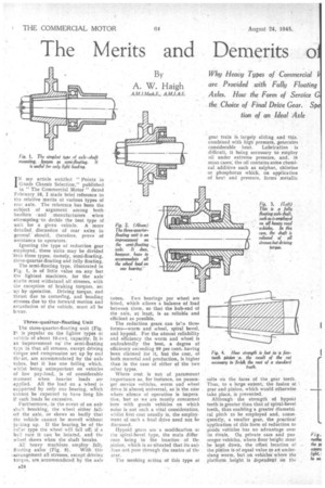
The semi-floating type, illustrated in Fig. 1. is of little value or& any but the lightest machines, for the axle shafts must withstand all stresses, with the exception of braking torques, set up by operation. Driving torque. end thrust due to cornering, and bending stresses due to the forward motion and retardation of the vehicle, must all be borne.
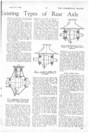
Three-quarter-floating Unit The three-quarter-floating unit (Fig. 21 is popular on the lighter types of vehicle of about 110-cwt, capacity, It is an improvement on the semi-floating typi in that all stresses, except driving torque and compression set up by end theist, are accommodated by the axle tubes, but it has one failing which, whilst being unimportant on vehicles of low pay-load, is of considerable moment when heavier loads are applied. All the load on a wheel is supported by only one bearing, wittich cannot be expected to have long life if such loads be excessive.
Furthermore, -in the event of an axle shaft breaking, the wheel either falls oft the axle, or skews so badly that the vehicle cannot be moved without ja7.king up. If the bearing be of the roller type the wheel will fall off; if a ball race it can be located, and thewheel skews when the shaft breaks.
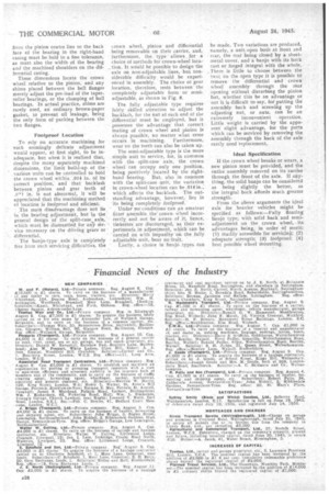
All heavy machines employ hilly floating axles (Fig. 3), With thi= -arra ugement all stresses, except driving torque, are accommodated by the axle tubes. Two bearings per wheel are fitted, which allows a balance of load
between them, so that the hub-end of the axle, at least, is as reliable and efficient as possible.
The reduction gears can taire three forms—worm and wheel, spiral bevel,
and hypoid. For the utmost reliability and efficiency the worm and wheel is undoubtedly the best, a degree of
efficiency exceeding 99 per cent, having been claimed for it, but the cost, of both material and production, is higher than in the case of either of the two other types.
Where cost is not of paramount importance as, for instance, on passen ger service vehicles, worm and wheel drive is almost universal, as is the case where silence of operation is impera
tive, but as we are mostly concerned here with goods vehicles on which
noise is not such a vital consideration, whilst first cost usually is, the employment of such a final drive need not be d iecussed.
Hypoid gears are a modification ol the spiral-bevel type, the main differ ence being in the location of thepinion, which is so situated that its axitloes not pass through the centre of the gear.
The meshing action of this type 01 salts on the faces of the, gear teeth. Thus, to a large extent, the fusion of gear and pinion, which would otherwise take place, is prevented.
Although the strength of hypoid teeth is greater than that of spiral-bevel teeth, thus enabling a greater diametrical pitch to be employed and, consequently, a smaller gear, the practical application of this form of redUction to goods vehicles has no advantage over its rivals. On private cars and passenger Vehicles, where floor height must be kept down, the offset location of the pinion is of equal value to an understung worm, but on vehicles where the platform height is dependent on the
diameter of the tyres, the advantages of an underslung worm or offset hypoid pinion are non-existent.
The spiral-bevel crown wheel and pinion are, by far, the most popular of rear axle reduction gears, despite the fact that tiny are the weakest and noisiest of the three types. They are comparatively easy and cheap to pro. duce, and work efficiently even when not quite accurately mounted. for instance, on a 3-ton lorry, the recommended backlash is 006-.010-in., but gears have been known to operate, with little additional noise and no apparent loss of efficiency, with as much as 022-in. backlash.
So long as the backlash remains constant, its value, up to the last figure quoted, for vehicles under 3 tons unladen weight, is not vital, but a variation in the figure beyond about .005 in. causes an increase in operating noise due to the fact that the Crown wheel wobbles as it revolves.
This irregularity can be caused by a number of factors, such as incorrect machining of the gear and of the differential housing on which it is mounted, but there is one factor whin affects it. that is not generally realized, and ttlat is the method of fixing the
gear to the differential-housing flange It has been general practice among many manufacturers in the past to employ rivets for this purpose, but experiments have shown that the unevenness of local pressure, due to riveting and the slight waviness of the flange and gear, are sufficient to cause a difference in backlash of .006 in.
This means that, for an assembly in which the initial gear adjustment allowed for is the minimum figure of .006 in., it can be reduced to nil, thus causing noise and rapid wear of the teeth. Bolting the housing and gear together, on the other hand, rarely causes more than .001 in. variation in backlash, and this can be ignored.
For a number of years, arguments have been carried on as to the most satisfactory minimum number of teeth in the pinion, some manufacturers employing six and others five. It would appear from experience gained on Service vehicles that the deciding factor is the undercutting of the pinion shank. Fig. 4 shows a five-toothed pinion, and indicates the cut necessary to finish the root of a standard tooth: it will be noted that the cutter actually gashes into a considerable portion of the shank if the latter be on the large side, and that the effective diameter at the heel of the tooth is a big reduction on the outside diameter. As a result, strength is lost, and it often happens that the pinion " wrings its neck" just behind the teeth.
Failures of this nature are encouraged by sharp corners on the leading edges of the teeth where they meet the shank, for, as is well known, stress concentrations are encouraged by sharp corners. Cracks are started which, in turn, result in complete. breakdown of the pinion.
One or two remedies are possible to correct these weaknesses. A radius can be incorporated on the tooth edge, but this must be a hand operation and, therefore, greatly increases the cost of the gears; a bastard set of gears can be cut in such a way that a false pitch for the pinion is created which increases the diameter at the pitch line and relieves some, or all, of the undercut. The teeth on the gear must, likewise, be set back so that correct meshing will obtain.
These two corrections do permit a greater stress to be accommodated by the gears, but, if they be systematically overloaded they will still continue to fall, in which case the only remedy lies in a decreased diametrical pitch and an increased diameter of the gears, which means a larger casing, or a double-reduction axle.
Quietness in any gear train depends. to a-great extent, on the rigidity of the mounting. Spiral-bevel gears exert. both thrust and separating forces when in action which tend to upset their correct Meshing, and it is, therefore, extremely important that care be taken in their mounting. On light machines it is permissible to house the pinion as indicated in Fig. 5, as the separating forces are comparatively small. It will be noted that the only support given is by the two shank bearings, which are widely spaced to provide maximum rigidity,
Heavy Vehicle Types Heavy vehicles, however, must have their pinions mounted with an outboard bearing, as shown in Fig. 6. In this case the two shank bearings are located close together in order that their bores may be accurately lined up with that of the outboard bearing. ,Were they spaced widely, as in Fig. 5. a slight deviation from the true centre line of all three bearings, when starting the housing bore, would result in considerable misalignment at the outboard bearing.
Manufacturers are particularly anxious that pinions should be accurately located relative to the axle centre line, so that correct meshing with the crown wheel can be ensured. They, therefore, fix its .position positively by mounting the shank bearing; in a separate sleeve which is pushed into the main casing, its position being regulated by aecurate machining and sometimes by the provision of shims. Thus, if for any reason the pinion has ta be removed, it must always be returned to exactly the same position, no deviation being possible,as would be the case were screwed adjustment provided.
The method by which accuracy of. crown-wheel location is to be obtained is a matter of opiniOn. makers differing in their ideas. Where the axle is of the split-case type, the only means for location and -bearing pre-load, is by accurate machining, or by shims between the two bells (Fig. 6). The distance Iron: the pinion centre line to the back face of the bearing in the right-hand casing must be held to a fine tolerance, as must also the width of the bearing and the machined shoulders on the differential casing.
These dimensions locate the crown wheel relative to the pinion, and any shims placed between the bell flanges merely adjust the pre-load of the taperroller bearings, or the clamping of ball bearings. In actual practice, shims are rarely used, an ordinary brown-paper gasket, to prevent oil leakage, being the only form of packing between the two flanges.
Foolproof Location
To rely on accurate machining for such seemingly delicate adjustment would appear, at first sight, to be inadequate, but when it is realized that, despite the many separately machined dimensions, the limit build-up of the various units can be controlled to hold the crown wheel within .014 in. of its correct position, and that backlash between pinion and gear teeth of
in. is not abnormal, it will be appreciated that the machining method of location is foolproof and efficient.
• The main disadvantage does not lie in the bearing adjustment, but in the general design of the split-case axle, which, must be dismantled for any s-eervice necessary on the driving gears or differential.
The banjo-type axle is completely free irom such servicing difficulties, the
crown wheel, pinion and differential being removable on their carrier, and, furthermore, the type allows for a
choice of methods for crown-wheel location. It would be possible to design-the axle on non-adjustable lines, but considerable difficulty. would be experienced in assembly. The choice of gear location, therefore, rests betweenthe completely adjustable form or semiadjustable, as shown in Fig. 8.
The fully adjustable type requiresfairly skilled attention to adjust the backlash, for the nut at each end of the differential must be employed, but it possesses the advantage that correct mating of crown wheel and pinion is always possib:e, no matter what error occurs in machining. Furthermore, wear on the teeth can also be taken up.
The semi-adjustable type is the more simple unit to service, for, in common with the split-case axle, the crown wheel can occupy only one position, being positively located by the righthand bearing: But, also in common with the split-case unit, the variation in crown-wheel location can be .914in.; which. affects the backlash. The outstanding advantage, however,. lies in its being completely foolproof. • Under no conditions can an amateur fitter assemble the' crown Wheel incorrectly and not be aware of it, hence, tinkerers are discouraged, as their experiments in adjustment, which can be carried on with impunity on the fully adjustable unit, bear no.fruit.
Lastly, a choice in banjo types can
be made. Two variations are produced, namely, a unit open both at front and rear, the rear being closed by a sheet. metal cover, and a banjo with its back cast or forged integral with the whole. There is little to choose between the two; on the open type it is possible tO remove the differential and crown wheel assembly through the rear opening without disturbing the pinion but, whether this be an advantage or not it is difficult to say, for' putting the assembly back and screwing up the adjusting nut, or nuts, can be an
extremely inconvenient operation. Little weight is carried by the apparent slight advantage, for the parts which can be serviced by removing the assembly through the back of the axle rarely need replacement.
Ideal Specification
If the crown wheel breaks or wears, a new pinion must be provided, and the entire assembly removed on its carrier through the front -of the axle. If anything, the solid banjo can be considered as being slightly the better, as the integral back affords much greater strength.
From the above arguments the ideal axle for heavier vehicles might be specified as follows:—Fully floating banjo type; with solid back and semiadjustment on the crown wheel, --its advantages being, in order of merit: (1) readily accessible for servicini; (2) adequate strength; (3) foolproof: (4) best possible wheel mounting.