


HIGHER • SPEEDS DEM BETTER BRAKING.
Page 54
Page 55
Page 56
Page 57
If you've noticed an error in this article please click here to report it so we can fix it.
The New Ideas of Engineers and Designers Vehicles and to Supplement nprove Upon Brake Mechanism of Motor )river's Power in Braking.
Ssteadily has the design of the commercial motor chassis advanced in respect of power unit, clutch, transmission, frame, steering gear, wheels and tyres that it comes rather as a surprise to find that in brakes alone the same rate of progress has not been maintained. To put the matter in another way, so much effort has been devoted to increasing the speed of the motor vehicle that there has been neither time nor opportunity, in full ineasure, to devote to the problem of rapid deceleration. Better and better roads, fewer dangerous curves and blind road junctions and other road improvements have found their counterpart in more reliable and faster vehicles. No wonder, then, that the designer of brakes has not been able to keep pace with the march of events. Transport operators hesitate less than they did to overload (and they' have never shown r great deal of reluctance in that direction!) and their drivers take advantage of the improved roads and road conditions and of the improved speed qualities of their vehicles to keep the throttle pedal well down. Hence the brake designer must feel that all mankind-.-all road transport mankind—is against him, whilst the only weapons at his command
are a few drums of meagre diameter, brake shoes with a tendency to bear at one Point along their length, and the inadequate power of the driver operating through a lever which, owing to the limitations of the driver's anatomy, has to be made all too short !
But the problem must be faced, for speeds of road vehicles will not diminish, their numbers will multiply faster than the road space can be provided for their accommodation, and the need for a greater power of rapid retardation will grow proportionately ; and the cry will be for more and better brakes. The discovery of the methods of making practicable the application of brake power to front wheels is an enormous help, so that, as confidence is developed in front-wheel brakes and drivers learn how to use them intelligently, we may look for an ever-increasing number of commercial chassis equipped for four-wheel braking.
A Consideration of _Braking Systems.
One . obtains a little encouragement in hoping for a steady improvement in braking from a study of the patent specifications. Without doubt many of the cleverest men in commercial motor engineering are at work trying to,give us better brakes than we are now using, and a careful study of their work, as revealed by their application for letters patent, shows that at least a dozen distinct lines of thought are being pursued. We will set these out first of all and then comment upon the examples that come under each head.
First we get the servo mechanism, the name coming from a Latin word and embodying the idea of getting somebody or something to do the work for you! With the servo mechanism a lead is given by the pressure of the driver's foot on the pedal, whilst friction, such as that produced by the gripping of a dutch or of brake shoes on a drum set revolving by the motion of the vehicle, produces the power which actimily pulls the braking surfaces into contact With one another.
Next we get the self-energizing brake, in which its own reaction—that is to say, the pull on its anchorage —acts in some form or manner to assist in brake hppli c32 cation. This pull can be employed to apply an additional brake., In the floating-fulcrum type of brake there is a selfenergizing effect, as, by allowing the fulcrum or hinge connecting the two shoes to follow the direction of the drum's rotation, there is produced a development of the grip somewhat resembling that produced when a rope is wound on to a rotating capstan. The capstan hand has but to put a slight pull upon the free end of the rope for the grip of the capstan to increase auto matically and enormously out of proportion to the man's own power. In the case of the floating-fulcrum brake the action is almost the same, the difference • being that the coil-gripping action takes place from within and not from without.
In the adjustable-fulcrum brake the object of the designer is to provide a means for adjusting the position of the fulcrum of the shoes relative to the rest of the brake mechanism, so that the ends of the shoes nearest to the fulcrum can be spread apart simultaneously, thus bringing the lining of the shoes into contact with the drum along its whole length. This is an obvious improvement, as the fullest possible length of life of the lining is obtained, whereas, as is well known, it is usual for the tips of the lining to be worn away And for many a lining—not an inexpensive item, by the way—to be discarded when only one-half of its possible life has been obtained from it.
Longer lining life is the aim of those who are endeavouring to use the flexible-band type of shoe working inside the brake drum. By its means longer contact is obtainable, and in this class Of brake a self-energiz ing effect in both directions is often attainable. The external flexible-band brake, by the way, can now be regarded as quite a back number in this country.
Brakes which act simultaneously both inside and outside of the same drum are not often to be met with, but there are recent indications that the type is being considered and studied closely.
Brakes which act in one direction only have certain
uses, and The Commercial Motor has long advocated
their adoption and use as the best form of spragging device, one which cannot be muddled or jumped. Such a brake prevents a vehicle from running away backward on a hill and it helps the 'driver to restart his vehicle on a hill. The type has a useful application for front wheels.
A. brake should not lock the wheel and definitely prevent it turning, for skidding wheels will not arrest the motion of a vehicle so quickly and so certainly as vell-gripped rotating wheels. Brakes which will not lock the
2 wheels are being considered by engineers.
In the case of the trailer, with considerable slack in the brake-operating mechanism between the driver of the tractot vehicle and the wheels of the trailer, the more-than-one-null brake is a necessity, and it has been employed with success on lorries. We expect to find It being more generally employed.
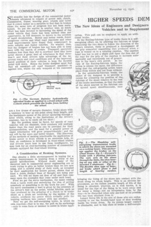
More and more attention is being directed towards means for assisting the power of the driver by compressed air or by a vacuum, acting on a piston or ,flexible diaphragm. In Germany a compressed-air brake has been adopted very largely..
Hydraulic pressure, obtained from a pump which Is
actuated either by .the engine of a vehicle or by any movement, backward or forward, of the vehicle, is also being used to assist the power of the driver.
The twelfth and last line of thought is a simple "booster," which, fitted between the brake pedal and the cam-operating levers, hastens up the first part of the movement, bringing into play a higher leverage ratio during that part of the movement which takes up slack and absorbs the clearance between shoes and drums, and, when this is done, gives the normal leverage ratio between pedal and brake shoes.
We do not propose to deal with all the efforts made in recent years—say, since the war—to follow these 12 lines of thought. It will suffice if we take examples of recent inventions which appear to us to have exceptional merit, and if we mention,as we pass along, those features in each class that we consider essential, referring also to those which are, to our way of thinking, undesirable.
Taking the servo type of assisting mechanism, we., hold that it should act whetther the vehicle be running forward or backward and that it should derive its power from such part of the transmission of a vehicle as is never capable of being separated from the road wheels. Obviously, it should not be operated-from the engine,' which would be liable to stop at a critical moment. The ability to act when the vehicle is running backward is vital. It is also essential that the driver should be able to apply the brake in the ordinary manner and quite independent of the action of the servo mechanism, whilst the power exerted by •the servo mechanism should he in direct relation to the power exerted by the driver.
Specific Examples of Modern Brake Design.
We illustrate in Fig. 9 a brake which has been designed by Dr. T. Blackwood Murray, of the Albion Motor Car Co., Ltd., in which the pressure from the pedal goes direct to a lever which transmits the greater part of the power to the brakes in the usual way, the remainder passing to a bell-crank lever, the function of which is to introduce friction between a constantly revolving disc and one carrying a pinion which engages two racks, one above the other. One of these racks must exert a pull on the brake no matter in which direction the disc is revolving at the time. The reason for the slots in the links is to allow only that rack to operate which is in the pulling position. In the Renault brake (Fig. 10) very much the same principle is employed, but, In this case, the disc is rotated by a worm and wheel, a screw on the shaft of the lever (A) taking ' the place of the bell-crank, whilst flexible cables are used instead of slotted links.
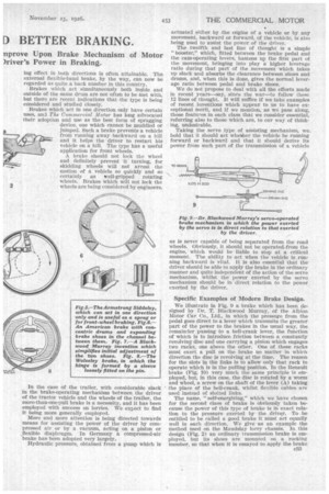
• The name, " self-energizing," which we have chosen for the second class of brake is Obviously taken because the power of this type of brake is in exact relation to the pressure exerted by the driver. To be entitled to be called a good brake it must act equally well in each direction. We give as an example the method used on the Maudslay lorry chassis. In this design (Fig. 2) an ordinary transmission brake is employed, but its shoes are mounted on a rocking member, so that when it is essayed to apply the brake
the rocking member attempts to lean in the direction in which the drum is revolving. At each end of a cross-shaft is attached an arm connected with the rocking member, and by an arrangement of dogs with a large amount of backlash, movement is transmitted to the cross-shaft and the wheel brakes are applied, no matter in which direction the rocking has taken place.
The Floating Fulcrum to Equalize Shoe Pressure.
There has probably been more effort applied lately to the type of brake which has a floating fulcrum than to any other. The object of this type of brake is that the fulcrum should not act as an abutment or anchorage, but that some alternative abutment should be met by the ends of the shoes where the expanding action takes place. This abutment can automatically change over to the end of the opposite shoes should the direction of rotation of the drum be reversed.
One of the best examples of this class is the invention of Mr. Guido Fornaca, the well-known Italian designer, In his brake, which we illustrate in Fig. 3, the ordinary expander cam is employed. Instead of acting directly on the ends of the shoes, it acts in a way that enables it to expand two linksthat are tied together at the top. These links are free to move in any direction, except towards the centre of the huh, from which it will be seen that they will allow either shoe to bear against the abutment provided, so producing the selfenergizing effect that is required.
There is a variation of the floating fulcrum type of brake in which the fulcrum or hinge between the two shoes may float, but where the expander cam is still used as the only form of abutment. A very good example of this class of brake is to be found on the Wolseley car (Fig. 8), the brake being more or less of ordinary construction, except that the hinge is formed by a sleeve which surrounds the pin fixed to the back plate, with a certain amount of play between the bore • of the sleeve and the pin, so that the sleeve is able to float and is not controlled by the pin. This particular form of construction, however, is adopted largely because it makes allowance for slight errors in machining, and only incidentally does it act as a self-assisting brake.
Adjustability of the Brake Fulcrum a Good Feature.
Of the brakes having an adjustable fulcrum, a very practical example is that designed, again, by Dr. T. Blackwood Murray, in which the shoes are provided each with a fulcrum pin, the pins being drilled and c34 tapped, one right-handed and the other left-handed (Fig. 7). A central anchorage is provided with a bearing for the bolt and for a worm, and a cap holds both in place. The bolt carries with it half a worm wheel, whilst the other half of the wheel is carried on a sleeve which is free to move on the bolt. The bolt and the sleeve are threaded so as to be screwed into the fulcrum pins. While assembling the brake mechanism adjustment is effected by means of the right and left-hand screws. When correct the worm is inserted, and thereafter all further adjustment will be equal on both shoes.
The Point in Favour of a Flexible Shoe.
The main object of the flexible-shoe type of brake is to increase the range of the bearing surface and, therefore, the length of the life of the brake, thus reducing to a minimum the cost of brake upkeep. We illustrate in Fig. t a brake of this type where a self-assisting . action is set up because the shoe has its anchorage only at the ends where they bear against the abutment; either end can meet the abutment according to the direction of rotation of t he drum, and as the tendency of the baud is to follow the drum, it expands with considerable pressure against the drum. The toggles which cause the expansion are operated by means of a looped link which spans the boss of the hubs.
FIMSSURE cauximmo VALVE
BALL VAAVe
41111NIII.
tviMti
We have referred to brakes that act both inside and outside of the drum, for it would appear as if attention is being devoted to the type, one of the best examples being from the designs of an American— Lorenzo Markham.. In his design the drum is formed in the shape of a channel with two concentric flanges. The shoes lie in the channel and are forced apart by expander cams which are coupled by means of a link, Which connects up to the operating levers. Springs are employed to bring the shoes together, so freeing them. from contact with the drum, and anchorage is effected by horn blocks, whilst the expander cam centres the shoes between the walls of the channel. Where the expander cam makes contact with the shoes rollers are mounted. This type of brake is illustrated hi Fig. 6.
One-direction Brakes.
The use to which brakes that act in one direction only can be put is limited, so that not a great deal of attention has been given to brakes of this kind. We give, however, in Fig. 5, an example designed by Armstrong Siddeley Motors, Ltd., in which a shoe of more or less ordinary design, although shorter, is anchored in the usual manner. A flexible band is also anchored at one end and extends around the greater part of the interior of the drum. In place of the usual cam there is a lever connected at one• end to the flexible band and, by means of a connecting rod, to the shoe. The self-energizing effect is obtained when the drum is rotated in the direction indicated in our drawing by an arrow, because not only does the flexible band tend to expaad, but it has an influence upon the pressure which is exerted on the shoe.
More attention should, in our opinion, be given to the type of brake that does not lock the wheels, the greatest need for this attribute being in connection with the application of brakes to front wheels. It is' known that the coefficient a friction between the
shoes and drum of a braking inechani.Fm increases appreciably with a decrease of speed, whereas the coefficient of friction between the tyres and the ground alters very slightly with a change of speed. Owing_ to this fact it is difficult for a driver to avoid locking his wheels in certain circumstances. A good example of what has been done to eliminate the fault is found in the design of the Daimler Motoren Gesellschaft. The brake shown of this design is of the hydraulic type, where a plunger applies the brake on the wheel itself. The front springs are mounted on shackles at both ends and are held from lateral movement by compression springs attached to the dumb-irons. When the retardation exceeds a predetermined resistance of the springs on the dumb-irons the springs become compressed, and, by means of a rod, close the valve, which reduces the pressure in the hydraulic cyiinder, so relieving the braking effort.
Lost Motion Between Pedal and the Brakeexpander Levers.
Loss of motion between the brake pedal or the brake lever and the brake-expander levers is one of the bugbears of the designer. To provide a ratio that Will give ample power would mean that the arc described by the lever would be so great that it would be uncomfortable, ineenvenient or even imposSible for a man to handle. The best way of overcoming this difficulty is, in the case of the brake lever, to enable the driver to take a second pull at his lever, and this, as we have said, is highly important in the application of brakes to a trailer. A type known as the Neat brake has been on the market for some years, whilst the more recent application of the principle of the two-pull is to be found in the Warben brake made by Mr. Len Ward. Some of the Yorkshire wagons have been equipped with levers which permit of a second pull, which applies the brakes after the first pull has taken up all the slack.
Pneumatic-pressure and Vacuum-operated Brakes.
In the case of brakes applied by pneumatic pressure or by a vacuum, it is important that there should also be some connection of a mechanical type, se that, should the vacuum or the air pressure fail, the driver would not be left in a helpless position, but would be able to apply his brake in tile usual way. It is important in our opinion, that the force of retardation supplied by pressure or vacuum should be in exact relation to the effort made by the driver. The control should not be the equivalent of the turning on of a tap, but the driver should be able to " feel " how hard he has applied his brake. The Dewandre mechanism may be taken as one of the best examples; it is so well known as to call for no description here. In the case of the Westinghouse brake, another extremely popular type, the driver is able to feel the amount of pressure he is applying.
We again emphasize the importance of the ability of the driver to "feel" his brake in the case of
hydraulic brakes, also the need for mechanical application as a standby should a serious leak cause the pressure from the hydraulic pump to escape. Some of the hydraulic brakes made, however, do not embody all these conditions. Most of the recent designs contain the same elements, viz., a geared pump driven from the propeller shaft, a pipe leading from it to a cylinder with an outlet from which the oil delivered from the pump can escape, a valve operated by the foot to close this opening against the pressure, and a piston in the cylinder which, when moved by the pressure, applies the brake. It will be seen that, in closing the opening of the pipe against the pressure, the driver has an exact indication of the pressure he is setting up in the cylinder. Some Of the designs embodying this principle have serious defects, as, for instance, the absence of any connection from the pedal. to the brake other than by means of the fluid pressure, whilst others will set up a vacuum instead of pressure in the cylinder if the vehicle should run backwards.
Letting the Driver " Feel " his Brake.
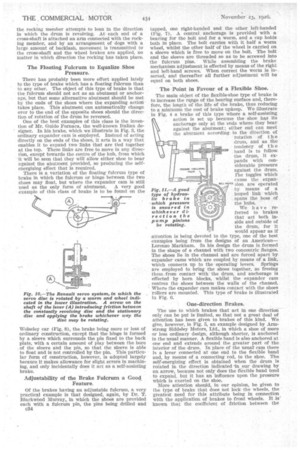
Of all the designs examined by us, we would place first that of Dr. Blackwood Murray as being the one containing the greatest number of good points. We have, therefore, chosen it as our example for illustration. The sketch (Fig. II), however, is purely iliagrammatical. The geared pump is fitted with four ball valves, so dial, no matter in which direction the pump may be revolving, a stream of oil is delivered to the
pipe. So long as the pressure-controlling valve is open there, will be no pressure set up in the cylinder, and, in consequence, the piston will not move, as the oil can escape freely through the presstre-controlling valve. When the pedal is depressed it acts upon the brake rod, and applies the brake by means of a rod which passes through, the cylinder. The lower end of the lever which forms the fulcrum exerts the pressure to close the valve, by so doing producing pressure in the cylinder and assisting the effort of the driver to apply the brake. Any oil that escapes thiiirgh the controlling valve comes back to the sump. Should the vehicle run backwards the suction of the pump becomes the delivery, and the delivery in turn becomes the suction side, the double set of valves being able instantly to accommodate themselves to the altered conditions, so that the flow is not affected by the reversal of direction in the pump.
Amongst the other designs that comply to a degree with our stipulation R are those of Ferdinand Godau, of Ghent, and. the Maybach Motorenbau. In the case of the latter design the circulation of oil is used for cooling and for clutch operation.
There is no need for us to-discuss' here the use of front-wheel brakes, which by now may be considered to have passed the stage of discussion. Many of the systems outlined by us are equally applicable to frontwheel brakes as well as to rear-wheel brakes, and it will be interesting to watch, in the course of the next year or two, the application of -new ideas .to braking systems.