


Independent Alternative Brake-operating Mechanisms
Page 32
If you've noticed an error in this article please click here to report it so we can fix it.
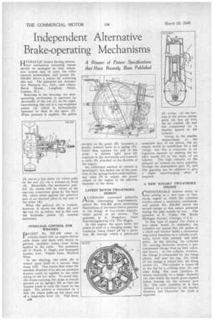
HYDRAULIC brakes having alterna'five mechanical actuating means should be arranged so that whichever system may be used, the other remains undisturbed, and patent No. 516,951 shows a means for achieving this end. The patentees are Automotive Products Co., Ltd., and others, Brock House, Langham Street, London, W.1.
Referring to the drawing, the shoespreading mechanism is operated by movement of the rod (I) to the right. Surrounding this rod is a cup-washered piston (2) which is hydraulically operated by fluid in the space (7). When pressure is applied, the piston
(2) moves a free slider (4) which pulls on the rod (1) via a screwed-on head (3). Meanwhile, the mechanical pullrod (5) stands still by virtue of the one-way connection given by the head (0), which abuts against the spherical seat of an inserted piece in the end of the slider (4).
When the pull-rod (5) is worked, however, it moves the slider (4) and the rod (I) as before, but in this case the hydraulic piston (2) remains stationary.
OVERLOAD CONTROL FOR WINCHES
PATENT No. 517,130 refers to vehicles fitted with an engine-driven cable drum, and deals with means to prevent excessive stress from being applied to the cable. The patentees are 0. North, P. Hugh, and Scartunell Lorries, Ltd., Tolpits Lane, Watford West.
In the drawing, the cable (5) is wound upon itself in a narrow deep drum (10). This means that when the smallest diameter is in use, an excessive tension could be applied to the cable owing to the low ratio. To avoid this, the frame carrying the drum is loosely pivoted on an upright (6) so that the tension tends to rock the frame to the right. The motion is restrained by a link (4) which pulls on the short end of a large-ratio lever (1). This lever,
430 pivoted on the point (2), transmits a greatly reduced force to a spring (7), which thus opposes the pull of the cable. A further light lever (8) responds to the movement and controls a cable (9) attached to the throttle of the engine.
An additional method of control is mentioned; this makes use of the position of the spring-loaded cable-restraining arms (3) to adjust the power output of the engine to the effective diameter of the drum.
LATEST DUTCH TWO-STROKE , DESIGN
A LTHOUGH conceraed primarily rt with scavenging improvements, patent No. 515,466 gives interesting illustrations of the latest Dutch practice in the design of two-stroke engines, either petrol or Ail driven. The patentee is A. Bargeboer, dude Scheveningsheweg 112, The Hague.
In this engine, the space under the piston is used as a charging pump, the crankcase being closed off by a partition (4) through which a piston-rod (5) works. At the bottom of the stroke, piston ports (4) line up with the air conduit (3) and the compressed air is thereby passed to the cylinder.
Owing to the smaller displacement of the underside face of the piston, the air supply would be insufficient for a full charge, but this is overcome in an ingenious manner by making the air inlet nozzle (1) in the form of an injector. The high velocity of the pumped air induces an extra quantity through the atmospheric port (2), and this quantity can be adjusted to give a • slight supercharging effect if required.
A NEW ROTARY TWO-STROKE ENGINE
CONSIDERABLE interest seems to be arising in a new type of twostroke engine in which the cylinders revolve about a stationary crankshaft, and patent No. 516,201 shows the second design of this nature patented during the past month or two. The patentee is F. Voiles, 750, North Michigan Avenue, Chicago, U.S.A.
In this type of engine (for which a new name would be desirable) the cylinders are spaced like the spokes of a wheel and revolve inside a stationary ring which functions as a cylinder-nead, being fitted with exhaust arid inlet ports. In the drawing, the cylinder (7), moving clockwise, receives a precompressed charge from an inlet valve, not shown. As the cylinder revolves, the charge is compressed by the rising piston, and near the top, the whole of the charge is forced into the firing pocket (1). The cylinder is closed off at the top by a rocking vane (2) and after firing, this vane (position 3) moves outwardly to a larger diameter (4) into which the burnt gases expand before leaving via the exhaust port (5). The vane (position 6) is then reclosed by a reversion to the smaller diameter and thereafter the cycle is repeated.