


THE DISTRIBUTION OF BRAKING POWER.
Page 32
If you've noticed an error in this article please click here to report it so we can fix it.
A Résumé of Recently Published Patent Specifications.
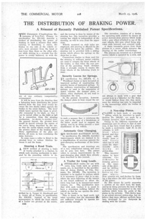
THE -Compagnie d'Applications Me' caniques, of Ivry-Fort, France, in specification No. 231,183, describe a method of distributing the power of braking in such a manner that while turning, or describing a curve, the brakes on one side of the vehicle receive more pressure from the hand or foot lever than those on the other side, yet while driving in a straight line the power is evenly balanced, as with the
use of any ordinary compensating arrangement.
It will be seen from the drawing that a balancing beam distributes the power derived from the foot lever evenly between the two shafts which operate the brakes in the usual fashion. The lever which bears against the beam is pivotally connected to its shaft, so that it van be moved either to the right or left by A connection from the steering mechanism. As shoWn in another view, the general layout, the pivoted lever would be moved towards the centre of the curve being described by the car, so that the inside wheels would receive the greater share of the braking effect. Many applications of the plan are shown, all more or less containing the same features.•
In some eases a roller is fitted to the pivoted lever to reduce friction between it and the beam.
Steering a Road Train. A_ NEW method of steering a train of trucks attached to a tractor, in which each steering mechanism is operated by the preceding vehicle is de
scribed by A. Venue, G. Riechiardi and A. Aretto, all of Turin, in specification Na. 234,819. Instead of the usual arrangement in which the front wheels of a trailer are pivoted at the centre, and the towing is done by means of the steering bar, this invention provides a towing bar which is independent of the steering, as will be seen from the upper view.
Wheels mounted on stub axles are employed, old steering is effected by the rod which lies below the pull-bar. The steering rod is provided with a sliding device which allows the springs on the draw-bar to play.
Connections similar to those used for the steering of ordinary motor vehicles are used to actuate the front wheels of the trailer, so that when the rear portion of the preceding truck deviates from a straight course it causes the front wheels of the following truck to steer. •
Security Leaves for Springs.
IN rpecification No. 247,074, G. A. Woodhead claims to have invented an improved method of constructing the security leaves of laminated springs. In the ordinary construction of laminated springs, as used in the suspension of motor vehicles, the damper plate, or plates, when employed, do not tend to strengthen the eyes.
In the present invention, however, the damper plate is bent round the eye in such a manner that it reinforces the eye, and in the case of a breakdown of the latter would tend to support the spring, and, by so doing prevent a total disablement of the vehicle.
Automatic Gear Changing.
SIR RICHARD MATTHEW RUCK, in specification No. 244,583, describes improvements which are claimed to be a simplification of previous patents for gear-changing mechanisms of his invention.
The specification and drawings are of a ye/7 complicated nature and need not be gone into here. The patent refers to certain improvements on the gear-changing plan which have already been described in this journal.
A Trailer for Long Loads. A STEERABLE trailer for use with extra long loads such as girders, masts, etc., is described in the specification of Anton Mattes, of Elm, Germany, No. 247,061. The invention is intended to be applied to trailers which it is necessary to steer—that is to say, where the mere following of the tractor is not found sufficient to allow the extra long load to be manmuvred round
corners, etc. The specification says that with such trailers it is usual to have a steersman walking behind the vehicle go that he can operate the steering of the trailer.
This is found to be hard work, and when travelling fast the steersman s not sufficient strength to operate his gear quickly enough. The invention consists of a device for operating such trailers by means Of power derived from pinions which mesh with a gear wheel attached to one of the road wheels, this gear wheel being provided with internal and external teeth.
A chain transmits power from these pinions •tO a screw Which operates the steering of the trailer forecarriage.
The pinions are mounted on a pivoted carrier which is operated by a cord, and
are always in mesh 'with a gear that carrier *Alt It s.--iRocket for the chain. It would appear from this that movement for steering can only be imparted to the forecarriage while the trailer is travelling.
A Non-slap Piston.
CLAIMS to have made a non-slap platen, which he describes in speci• fication No. 246,941, are made by a German inventor, Paul Schattler.
Owing to the different expansion of aluminium and its alloys to that of cast iron, it has been found that if a piston be made a moderately tight fit in its cylinder, it will bind when heated, and that if made sufficiently loose to work freely when hot it will cause the objectionable noise known as piston-slap.
This inventor claims to have
oVercorne t li e difficulty by forming grooves on the inner side of the skirt. and by drilling a number of holes at the place where • flea.: grooves are, and further by form ing a slot where the skirt joins the head of the Piston • By this means he partly separates a portion of the skirt from the head, and by so doing prevents the heat of the head from being transmitted to the two surfaces which form the guide of the piston in its cylinder. This device' may to an extent prevent piston-slap, but we believe that more efficient Methods have been developed by our designers iii dealing with the trouble.