


Patents Completed.
Page 22
If you've noticed an error in this article please click here to report it so we can fix it.
Complete specifications of the following patents will be sent to any address in the United Kingdom by the Sale Branch, Patent Office, Holborn, W.C., upon receipt of eightpence per copy.
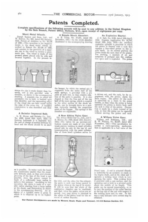
Sheet Metal Wheels.
Joseph Sankey and Sons, Ltd., and W. Burton, No. 293, dated 4th January, 1912, Patent, of Addition to No. 20,126 of 1908.—This invention is for improvements in the sheet metal wheels described in Patent No. 20,126 of 1908, and consists in the provision of a separate rim in the wheel to receive a pneumatic tire. The wheel is made of two pressed plates placed side by side and secured together. In the present in stance the rim is made deeper than formerly, and is also provided with a shoulder, as shown in the accompanying drawing. A separate rim, in which the pneumatic tire is held, is bedded upon this shoulder, and the upstanding edges of the wheel rim are bent round inside the edge of the extra rim. A modified construction is also described and illustrated.
A Daimler Improved Bolt.
L. H, Meyer, and Daimler Co., Ltd., No. 4340, dated 18th April, 1912.—In forming boltheads it is desirable that the rate of change of section between the head and the shank should be as small as is possible. In motor work the heads are considerably smaller than the standards hitherto used, so that semi-circular grooving of the face of the head is not possible, since the groove cannot be made of a sufficiently large radius to achieve this purpose. According to this invention, the curve is made of a variable radius starting from a large radius at the shank, and diminishing as shown in the accompanying drawing. An instance of a suitable curve is given in which it is elliptical up to its highest point.
A Simple Shock Absorber.
A. E. Terry, No. 27,561, dated 8th December, 1911.—In the shock absorber illustrated in the accompanying drawing tha hanger, by which the central pin is supported from the lower half of the main springs, is provided with a pin joint at each end, so that relative rotation of the parts is possible. It is also shaped so that the free end of the to half of the main spring, which is coupled to the other section of the shock absorber, can be brought down to a position vertically beneath the suspension point of the hanger. The springs in the absorber are adjustable.
A New Albion Valve Gear.
The Albion Motor Car Co., Ltd., and T. B. Murray,No. 1429, dated 18th January, 1912.—The valves for an internal-combustion engine are made of two simple trunk pistons working in small cylinders placed side by side at the top of, and communicating with the main cylinder. One of these small cylinders serves for the inlet, and the other for the exhaust, the ports in each ease being opened by the piston when at the top of its stroke. It will be seen that the whole of the combustion chamber can be machined, and that, when the piston valves are removed, very easy access is obtained to the whole of the piston head for the removal of carbon deposits.
An Explosion Starter.
J. D. Bell, No. 9139, dated 18th April, 1912. Cognate Application No. 16,763, dated 18th July, 1912.—An auxiliary explosion cylinder is provided in which the piston is formed with a rack that engages a free-wheel pinion on the engine shaft. In its normal position the piston holds the rack clear of the pinion. For starting, a mixture of air and acetylene is pumped into the combustion space and is exploded. The piston is driven out, and the rack, by its engagement with the pinion, starts the main engine. The piston (or the rack) 's connected by a chain to the pump handle, so that when the pump is being operated the piston is drawn back until the rack is clear of the pinion. Connection is made by a chain instead of Iv rods so that the pump can be operated without moving the piston and rack.
A Winans Valve Gear.
Willans and Robinson, Ltd., and K. W. Willans, No. 26,637, dated 28th November, 1911.—This specification describes a valve-operating mechanism that is applicable to a fuel valve of the Diesel type. A rod is actuated directly or indirectly by an eccentric or crank on the engine shaft, and at the other end it operates a rocking lever which in turn operates the valve. This rocking lever is provided with a cam surface, and the operating rod is held in a. pivoted guide about the middle of its length. This guide can be moved transversely, so as to vary the position of the roller bearing at the top end of the rod with respect to the rocking lever and its CamIn this way a very delicate valve control may be obtained.