


A.E.C. TURNS T
Page 42
Page 43
Page 44
Page 45
If you've noticed an error in this article please click here to report it so we can fix it.
THE FLAT
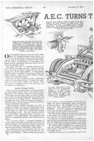
0 liTSTANDINCi features of the new A.E.C. Regal Mark IV underfloor-engined coach chassis, are that it will provide for a body of increased seating capacity, greater accessibility is afforded to the engine. and the system of fuel-injection in conjunction with 'engine location considerably reduces the noise in the cab and in the passenger saloon.
The power unit used is a modified version of the A.E.0 9.6-litre oil engine and this is off-set-L----mounted on its side with the heads coming well clear of, and beneath, the off-side frame member. In this position complete access is provided to the injectors, timing and other . auxiliaries, which are locatedbehind a hinged valance in the side of the body.
Some idea of what is meant by greater accessibility is shown'by some typical timings. To remove the engine takes 13 minutes. and to replace it 24 minutes. Only 3i minutes are required to remove the fuel pump, and five minutes for the injectors.
Built-in Lifting Tackle
Engine removal and replacement are greatly simplified by incorporating suitable tackle in the chassis design. Operated by the wheel-nut brace, the tackle comprises a screw gear and two chains which run from a bridgepiece on the screw head, through holes in the frame, and over sprockets to an engine bracket. When free of its mountings and other chassis connections, the engine is balanced about a lifting eye-pin connected to the hoist.
and can be lowered to the ground. .
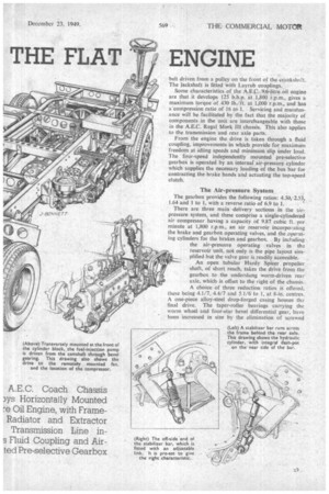
A.E.C.-Metalastik flexible mountings are used to suspend the engine, the front mounting-bracket which is bolted to a frame side-member, supporting the front of the engine by means of a large-diameter bonded
rubber-and-metal bush. The rear mounting consists of a large-dialmeter cross-tube bolted at one end to a bracket on a frame side:-Member, and supported at the other by a swinging link which is rubber bushed top and
bottom. .
The cross-tube carries a V-shaped mounting of bonded rubber and .metal in which the rear end of the engine is housed. Fore and aft movement is restrained by a link mechanism incorporating rubber bushes, and engine torque-reaction is absorbed by rubber buffers.
An important feature in connection with the fuelinjection equipment is that the pump provides for twostage or pilot injection. Without going into the theory a8
of this system, it can be said that its chief aim is to reduce the rather objectionable knock characteristic of the oil engine. The equipment used is made by C.A.V. Ltd., under licence from the Atlas Co., of Stockholm. The A.E.C. concern, in conjunction with C.A.V. Ltd., has been responsible for extensive development work with the system in this country.
The fuel-injection pump is mounted across the front of the engine, from which it is driven by spiral-bevel gear from the front of the camshaft.
A breakaway in radiator mounting is a notable point. This unit does not come above frame level, which means that the bodybuilder is given full scope in cab design to give a vastly improved angle of vision for the driver. The radiator block is supplied from a separate header tank, and cooling is assisted by an extractor-type fan which forms a close fit in a shroud mounted behind the radiator block The drive for the fan is by a jackshaft, which is twin belt driven from a pulley on the front of the cranksha ft. The jackshatt is fitted with Layrub couplings.
Some characteristics of the A.E.c. 9.6-litre oil engine are that it develops 125 b.h.p. at .1,800.i.p.m., gives a maximum torque of 430 lb./ft. at 1,000 r.p.m., and has a compression ratio of 16 to I. Servicing and maintenance will be facilitated by the fact that the majority of components in the unit are interchangeable with those in the A.E.C. Regal Mark 111 chassis. This also applies to the transmission and rear axle parts.
From the engine the drive is taken through a fluid coupling, improvements in which provide for maximum freedom at idling speeds and minimum slip under load. The four-speed independently mounted pre-selective gearbox is operated by an internal air-pressure cylinder which supplies the necessary loading of the bus bar far contracting the brake bands and actuating the too-speed clutch.
The Air-pressure System The gearbox provides the following ratios: 4.50, 2.53, 1.64 and 1 to 1, with a reverse ratio of 6.9 to 1.
There are three main delivery sections in the airpressure system, and these comprise a single-cylindered air compressor having a capacity of 9.87 cubic ft. per minute at 1,800 r.p m., an air reservoir incorporating the brake and gearbox operating valves, and the operating cylinders fot the brakes and gearbox. By including the air-pressure operating valves in the reservoir unit, not only is the pipe layout simplified but the valve gear is readily accessible.
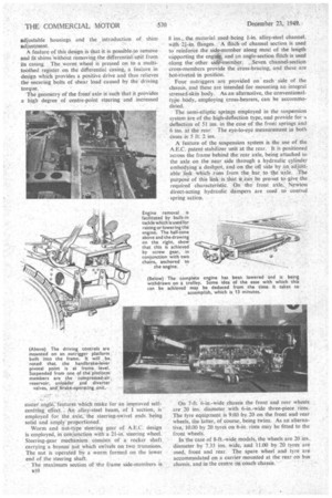
An open tubular Hardy Spicer propeller shaft, of short reach, takes the drive from the gearbox to the underslung worm-driven rear axle, which is offset to the right of the chassis. A choice of three reduction ratios is offered, these being 4.1/7, 4.4/7 and 5.1/6 to 1, at 8-in. centres. A one-piece alloy-steel drop-forged casing houses th final drive. The taper-roller bearings carrying the worm wheel and four-star bevel differential gear, have been increased in size by the elimination of screwed
adjustable housings and the introduction of shim adjustment.
A feature of this design is that it is possible-to remove and fit shims `without removing the differentialunit from its casing. The worm wheel is pressed on to a multitoothed register on the differential casing, a feature in design which provides a positive drive and thus relieves the securing bolts of shear load caused by the Tdriving torque.
The geometry of the front axle is such that it provides a high degree of centre-point steering and increased caster angle;leatures which make for an improved selfcentring effect. An alloy steel beam, of I section, is employed for the axle, the steering-swivel ends being solid and amply proportioned.
Worm and nut-type steering gear of A.E.C. design is employed, in conjunction with a 21-in. steering wheel. Steering-gear mechanism -consists of a rocker shaft carrying a bronze nut which swivels on two trunnions. The nut is operated by a worm formed on the lower end of the steering shaft.
The maximum section Of the frame side-members is B10 8 ins., the material used being i-in. alloy-steel channel, with 21-in. flanges. A flitch of channel section is used to reinforce the side-member along most of the length supporting the engin*. and an angle-section flitch is used along theother side:member. Seven channel-section cross-members provide the cross-bracing, and these are hot-riveted -in position.
Four outriggers are provided on each side of the chassis, and these are intended for mounting an integral stressed-skin body. As-an alternative, the conventionaltyPe body, employing cross-bearers, can be accommodated.
The semi-elliptic springs employed in the suspension system are of the high-deflection type, and provide for a deflection of 51 ins, in the case of the front springs and 6 ins, at the rear. The eye-to-eye measurement in both cases is 5 ft. 2 ins.
A feature of the suspension system is the use of the A.E.C. patent-stabilizer unit at the rear. It is positioned across the frame behind the rear axle, being attached to the axle on the near side through a hydraulic cylinder embodying a dashpot, and on the off side by an adjustable link which runs from the bar to the axle. The purpose of this link is that it can be pre-set to -give the required characteristic. On the front axle, Newton direct-acting hydraulic dampers are used to control -spring action.
On 7-ft. 6-in.-wide chassis the front and rear wheels are 20 ins. diameter with 6-in.-wide three-piece rims. The tyre equipment is 9.00 by 20 on the front and rear wheels, the latter, of course, being twins. As an alternative, 10.00 by 20 tyres on 6-in, rims may be fitted to the front wheels.
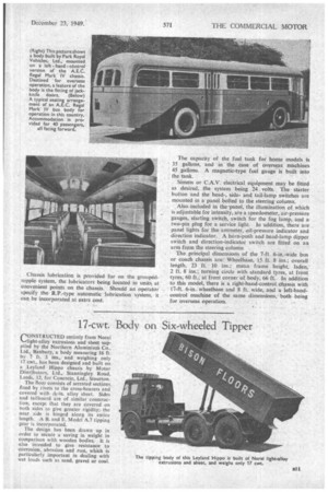
In The case of 8-ft.-wide models, the wheels are 20 ins.. diameter by 7.33 ins, wide, and 11.00 by 20 tyres are used, front and rear The spare wheel and tyre are accommodated on a carrier mounted at the rear on bus chassis, and in the centre 6n coach chassis: • The capacity of the fuel tank for home models is 35 gallons, and in the case of overseas machines 45 gallons. A magnetic-type fuel gauge is built into the tank.
Simms or. C.A.V. electrical equipment may be fitted as desired, the system being 24 volts. The starter button and the head-, sideand tail-lamp switches are mounted in a panel bolted to the steering'eolumn.
Also•included in the-panel, the illumination of which is adjustable for intensity, are a speedometer, air-pressure gauges, starting switch, switch for the fog lamp, and a two-pin plug for a service light. In addition, there are panel lights for the ammeter, oil-pressure indicator and direction indicator. A horn-push and head-lamp dipper switch and direction-indicator switch are fitted on an arm from the steering column
The principal dimensions of the 7-ft. 6-in.-wide bus or coach chassis are: Wheelbase, 15 ft. 8 ins.; overall length. 23 ft. 10 ins.; mean • frame height, laden, 2 ft. 8 ins.; turning circle with standard tyres, at front tyres, 60 ft.; at front corner of body, 66 ft. In addition to this model, there is a right-hand-control chassis with 17-ft. 6-in., wheelbase and 8 ft. wide, and a left-handcontrol machine of the same dimensions, both being for overseas operation.