


A Sleeve-valve Two-stroke Engine
Page 40
If you've noticed an error in this article please click here to report it so we can fix it.
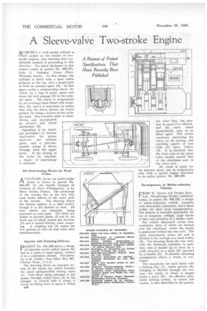
A Resume of Patent Specifications That Have Recently Been Published
Q.CARCELY a week passes without it L./new patent on the subject of twostroke engines, thus showing that considerable research is proceeding in this direction. The latest disclosure in this respect -comes in patent No. 495,371, from G. Ga.hagan, Green Place, Wonersh; Surrey. • In this design, the cylinder is fitted with a liner which -prOjects, at the top, into a large? ,bore to form an annular space (3). In this space works a reciprocating sleeve (4) which, by a ring of ports, opens and closes the inlet passage (5) to the cylinder space. The sleeve is reciprocated by an overhead shaft fitted with eccentrics (2), and it is important to realize that only the sleeve moves, the centre portion (1) being a fixture on the cylinder head. The eccentric shaft is chaindriven, and incorporatei
an advance and retard mechanism (6).
Operation is 'on standard principles ; at bottom dead-centre the piston uncovers the exhaust ports, and a pre-compressed charge is blown through from the upper ports. If the closing of the latter be retarded, a degree of supercharge is obtained.
All-wheel-steering Device for Road Trains.
A COUPLING device for multi-trailer
trains is shown in patent No. 494,387, by the Societe CentRile de Chemins de Feret d'Entreprises, of Le Mans, Sarthe, France. The advantage of the scheme lies in the fact that each trailer follows in the exact path of the tractor. The drawing shows the scheme applied to a light trailer, though it is not limited to such. All four wheels are steerable, being . mounted on stub axles. The latter are linked to pivoted plates (2 and 4) the front one of which carries the drawbar (1) and is turned thereby when cornering. A coupling rod (3) unites the two systems so that all stub axles steer simultaneously.
Injector with Pulsating Delivery.
PATENT No. 494,238 shows a design of injection nozzle which injects the fuel in a series of rapid spurts, instead of in a continuous stream. The patentee is M. Feidler, Post Office Box 367,
Chester, Penn.,•
The drawing shows an enlarged section of the nozzle tip, which includes the usual spring-loaded closing valve (1). Fuel flows along passages 2 and passes through radial bores (3) in the plunger, to central hole 6 where it exerts its lifting force in space 5. When
£38
• the valve lifts; the pressure in space 5 Is relieved, and the valve closes momentarily, only to be lifted again. This action continues, chattering the valve on its seating, and expelling spurts of fuel from the spray orifices (4). It is, -essential that the total area of the spray holes should exceed that of the maximum area of the valve seat.
No claim is made for the injector alone, but in conjunction only with a special engine described in an earlier patent, No. 390,190.
Developments in Refuse-collection Vehicles.
CROM W. Dawes and Dennis Bros., 1 Ltd., Woodbridge Works, Guildford, comes, in patent No. 495,122, a design of refuse-collection vehicle, complete with detachable containers, and a hand trolley for their local transportation. The scheme is intended principally for use at hospitals, colleges, large blocks of flats and premises of a similar kind.
The vehicle illustrated carries four containers, three of which are located over the wheelbase, whilst the fourth is positioned behind the rear axle. The space immediately above the axle is allotted to the carriage of a hand trolley (4). The drawing shows the rear view, with the hindmost container in position; this is hauled up or down by a cable attached to a shaft (2) operated by a handle (3). A selective clutching arrangement allows a choice of container.
The receptacles are each fitted with a loading flap (1), whilst gravity discharging is effected through the bottom, the whole of which is hinged about a pivot (5). An effective automatic locking system, to ensure safe transit, is also described in the patent.