


AN INGENIOUS ONE-WAY AGRIMOTOR.
Page 32
If you've noticed an error in this article please click here to report it so we can fix it.
A Résumé of Recently Published Patents.
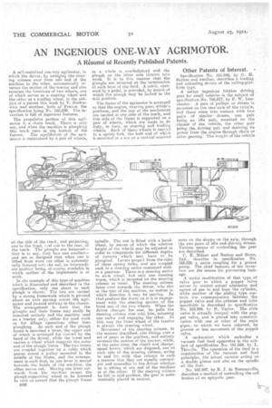
A self-contained one-way agrimotor, in which the driver, by swinging the steering column over from one end of the machine to the other' automatically reverses the motion of the tractor and also reverses the functions of two wheels, one of which serves as a steering wheel and the other as a trailing wheel, is the subject of a patent this week by V. Dutkiewies and another, both of France, the specification. being No. 165,830. The invention is full of ingenious features.
The propulsive portion of this agrimetor is a chain track. There is only one, and when the machine is ploughing this track runs in the bottom of the
furrow. The equilibrium of the agsimotor is maintained by a pair of wheels,
at the side of the track, and projecting, one to the front, s 'id one to the rear, of the track. The ploughs are balanced— that is to say, they face one another— and are so designed that when one is lifted from wore the other is automatically lowered into the soil, an intermediate position being, of course, available in which neither of the implements is at work.
. In the example of this type of machine which is illustrated and described in the specification, only one share to each plough is shown. The two are carried by a strong framework which is pivoted: about an axle passing across the agrimotor and located midway in the chassis. The arrangement is such that the ploughs and their frame may easily be removed entirely and the machine used as a tractor only, either for road work Or for tillage operations other than ploughing. , At each end of the plough frame is mounted, a lever, the upper end of which is arranged f or control by the Rand of the driver, while the lower end carries a wheel which supports the outer end of the plough frame. The two levers are coupled together by a cable which passes round a pulley mounted in the inidelle of the frame, and the arrangement is such that, as one lever is moved towards the inside of the machine, tho other moves out. Moving one lever outwards from the machine causes the plough-supporting wheel to be lowered to such an extent that the pleugh frame
1136 as a whole is overbalanced and the .plough on the Other side thrown into work. It is in this manner that the ploughs,are reversed at the termination of each bout of the field. A catch, operated by a pedal, is provided, by means of which the plough may be locked in the mid position.
The frame of the agrimoter is arranged se that the engine, steering gear, driver's platform, and the rest of the mechanism are carried at one side of the track, and this side of the frame is supported on a pair of wheels, which are made to do duty, in turn, as steering and trailing wheels. Each nf these wheels is carried in a spring fork, the butt end of which is mounted on a nut on a vertical screwed
spindle. The nut is, fitted with a handwheel, by means of which the relative height of the whetls may be adjusted in order to compensate for different depths 'of furrows which may have to be ploughed. Levers project. from the sides of these spring forks, and are coupled each to a steering sector contained within a gearease. There is a steering sector to each wheel, but only one steering worm, which is mounted on the steering column as usual. The steering column leans over towards the driver, who sits at the rear of the machine, no /natter in which direction it may be moving. In that position the Worm on it is in engagement with the steering section of the front one of the two wheels. When the driver changes Ins seat, he pulls the steering column over with him, releasing one sector and engaging the other. In this way the front wheel of the tractor is always the steering wheel.
Movement of the steering column, in the manner described, also swinge over a set of gears in the gearbox, and entirely reverses the motion of the tractor, while, at the same time, the clutch and change. speed levers, which are disposed, one at each side of the -steering column, awing to and fro with that column in such a manner that they are equally convenient and accessible to the driver whether he is sitting at one end of the machine or at the other. If the steering column be left in mid' position, the gear is automatically placed in neutral.
Other Patents of Interest. •
Specification No. 165,942, by G. H. Barnes and another, describes a loading and unloading device of the rolling-platform type.
A rather ingenious friction driving gear for small vehicles is the subject of specification No. 166,017, by F. W. LanChester. A pair of pulleys or drums is mounted on the tear axle of the vehicle, and these come into contact with two pairs of similar drums, one pair being an idle pair, mounted on the chassis of the vehicle, the other pair being .the driying pair and deriving ite power from the engine through chain or other gearing: The weight of the vehicle rests on the drums on the axle, through the two pairs of idle and driving drums. Various means of controlling the gear are described.
C. E. Milner and Tienton and Stone, Ltd., describe in specification No. 166,026 a union coupling for a grease pump. The chief features of the invention are the means for preventing leakage.
A useful modification of that type of valve gear in which a poppet valve serves to control actual admission and egress of gas to and from the cylinder, while another of the sliding type con trols the communication between the poppet valve and the exhaust and inlet manifolds is described in specification No. 165,904, by H. Taylor, The slide valve is actually integral with the poppet valve, and is placed into communi cation with one or other of the main pipes, to which we have referred, by greater or less movement of the poppet valve.
A carburetter which embodies a vacuum fuel feed apparatus is the sub ject of specification No. 161,554, by L.
Thivolle. The operation of the feed is a combination of the vacuum and float ptinciples, the actual vacuum acting on a double piston and also on the spindle of the float.
No. 165,847, by E. J. de Normanville, describes, a method of controlling the coil brakes of an epicyclie gear.