


Inventors Turn to Disc Brakes
Page 41
If you've noticed an error in this article please click here to report it so we can fix it.
A LTHOUGH the disc brake is 1-1 extensively used on aircraft, so far it has made little progress on road i chicks. In terms of brake-facing area, that of the disc brake can he increased
ithout adding unduly to the overall dimensions of the brake assembly. In the case of the conventional shoe brake, limitations are imposed by the drum diameter in relation to the wheel, and on drum depth by clearance and other factors.
In theory, at least, the disc brake would seem to offer the advantages of providing a greater friction-surface area within a brake assembly of moderate dimensions, which should, in effect, reduce the tendency to brake fade.
The interest taken in disc-brake design can he gathered from the many features which arc covered every month by patents. The three dealt with here will give some idea of the possible trends, particularly as concerns the method of operation.
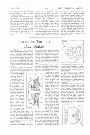
From the Dunlop Rubber Co., Ltd., 1 Albany Street. London, N.W.1, and others, conies patent No. 688.382, which states that the normal type of drum brake cannot pro, vide the torque necessary to brake the heavier and faster types of vehicle now being made. The main reason for this is that all the heat generated is confined inside the drum, which leads to high temperature and consequent fading of the braking. The improved brake shown is constructed so as to give ,a high degree of cooling.
The drawing gives an idea of the main point of the design. The rcvolv
ing member consists of a disc (I) which is enveloped over a small part of its periphery by a group of three hydraulic
cylinders (2). These each contain a pair of pistons faced with friction material, one on each side of the rotary disc. When the cylinders are energized, the disc is firmly pinched between the sets of pistons to give the braking effort.
By concentrating the braking action on only a small part of the surface of the disc, the remainder revolves in free air and is thus enabled to dissipate the heat instead of storing it.
According to patent No. 687,578, disc brakes are given to making " cl unking " sou nds during a reversal of vehicle direction, and to prevent this is one of the objects of the design shown in the patent. The patentee is Lambert Brake Cor, poration, St. Joseph. Michigan, U.S.A.
The brake shown is operated hydraulically from the driver's pedal, and creates its own servo amplification. The rotary member is a twopart drum (I) united by bolts round the periphery. The braking surfaces of this drum are engaged by a pair of discs (2 and 3) faced on their outer surfaces. with friction material. The discs are slidable in an endwise direction, and have a limited rotational freedom with respect to each other.
Such rotary motion causes balls (4) to ride up sloping ramps and so spread the discs into braking contact with the drum. The rotary motian is imparted by a pair of hydraulic cylinders (5 and 6) which act in unison When the pedal is depressed. The hydraulic pistons act on lugs which stand out from the discs. To prevent any suggestion of thump when the vehicle is reversed, the stop faces of the disc lugs are fitted with rubber buffers.
A disc brake is shown in patent No. 689,552 which comes from H. Kniepkamp, 12 Alle, Heilbronn-amNecker, Germany. The brake described is of the type in which the active surfaces occupy only a portion of the total circle, leaving the Test to act as a cooling surface.
Referring to the drawings, a totally enclosed drum contains a pair of segments (I and 2) each faced with friction fabric. Normally clear of the sides of the drum, they are expanded into rubbing contact therewith. The operating control is a finger (3) which, by pressing on one of the segments, causes it to move with the drum. When this occurs, it rolls on balls (4) which, by acting on the sloping faces, spread the segments. This is shown in the lefthand drawing, which is a development of the segment area