


A FRICTION-DRIVEN TRACTOR.
Page 22
If you've noticed an error in this article please click here to report it so we can fix it.
A Résumé of Recently Published Patent Specifications.
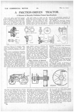
This week, again, agricultural tractor patents dominate the field. No. 125,005, by W. L. Bodman, is particularly interesting, and possesses many novel leatuves. It is a machine of the most modern type. that is to say, small, with light moving pats, totally enclosed, and without a frame as is normally understood when referring to a. chassis. The engine, •crankcase,, gearbox, etc., combine to perform the function of a framework.
This tractor is particularly interesting on account of its transmission, which includes a friction gear and final drive thiough shock-absorbing springs. The engine drives direct through a universally-jointed shaft to another short horizontal shaft carried in a bracket which is mounted in a vertical pivot immediately below the middle of the length of this shaft. On the shaft iteelf are two driving friction discs equally spaced from this central pivot. Slight movement in either direction of the shaft about its pivot brings bqth driving friction-discs into contact with the two driven discs, and these are keyed each ,to a driving shaft of a road wheel. The driving discs are, of course, slideable on their Shafts% so as to effect changes in gear ratio.
There are no springs-or other similar de, vices employed to keep these discs in contact with one another, this being effected by means of a hand level woel. ing over a quadrant -similar to those customarily employed in connection with hand-brake gear*, an indicator being provided to show the driver the amount of pressure which he is causing between the disCs.
652 The main shafts on which are the driven discs, are not-secured to the road wheels, but carry on their outer ends eccentrics. On the outsides of these eccentrics, and bearing on them as do eccentric sheaves, are two spur pinions, and these again mesh with internally cut
gears slightly larger in diameter, the difference in size being in accordance with the total gear ratio required. As the axle shafts revolve, therefore, these gear pinions, acting under the influence of the eccentrics and of the internal gears with which they are engaged, revolve, but more slowly than the driving shafts. Flanges on the spur pinions carry spiders, the outer ends of which are coupled, as shown on one of our illustrations, through the medium of coiled springs to the rims of the road wheels.
Other Patents of Interest.
No. 124,934, by A. Nicholson, is a tractor coupling;•-..which is formed in two parts, which are united by a type of bayonet joint embodying a quick thread screw. This joint tends to break as the
load comes on, but disunion is prevented by suitably arranged springs until a piedetermined limit of stress is exceeded.
No. 124,186, by an American patentee. R. E. Fielder, is an arrangement of internal gear drive axle, with the driving pinions, which mesh with internail:, -cut gears in the road wheels, vertically under the hubs of those wheels. The easing for the driving axles and differential gear actually supports the load through the usual epring.s. The object of this arrangement is to reduce the level of the loadline of the vehicle, and it ap
psers to be particularly adaptable for use on public service and other passengercarrying vehicles.
No. 124,818, by Lieut.-Col. Ruston, adds to the power of an engine of given external dimensions of the cylinder, by reducing the clearance and adding an in dependent compression and combustion chamber.
No. 124,918, by the Austin Motor Co., mounts a gearwheel on a shaft, by forming an eccentric solid with the latter, a corresponding recess of similar shape in the former, and bolting the two together. By providing a slight clearance in the bolt hole in one of these components, a little relative movement is allowed, and this has the effect of wedging one part tightly against the other.
Steering gear for a trailer whereby it will automatically track with the hauling vehicle is the subject of No. 124,929, by K W. le Tall. Holley Bros., Ltd., of 'Coventry, in No. 124,933, embody certain _modifications of that type of carburetter in which fuel is supplied through a restricted on fice to a well, the object being mainly the simplified and economical construction of such carburetter.
In No. 125,009, Alldays and Onions, Ltd., describe an improved flexible coupling of the type embodying a number of leather or fibre rings attached to spiders on the driving and driven shafts. The particular object of this in-vet-Amu is to allow ,endwise movement, of one of the shafts. ae is required in the case of a clutch shaft, without the risk of thespider binding on its key or spline. Three spiders are used.