


Worm Contact.*
Page 16
Page 17
Page 18
If you've noticed an error in this article please click here to report it so we can fix it.
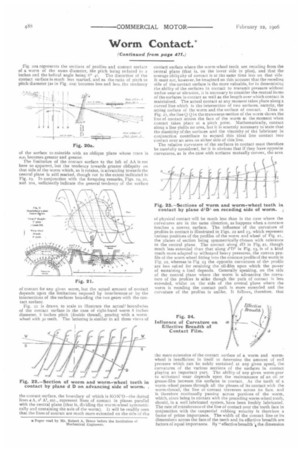
Fig. 20s represents the sections of profilesand contact surface of a worm of the same diameter, the pitch being reduced to inches and the helical angle being 6" 41. The distortion of the contact surface is much less marked, and as the ratio of pitch to pitch diameter (as in Fig. 2oa) becomes less and less, the tendency of the surface to coincide with an oblique plane whose trace is gitli becomes greater and greater.
The limitation of the contact surface to the left of AA is not here so apparent, but the tendency towards greater obliquity on that side of the worm which, as it rotates, is advancing towards the central plane is still marked, though not to the extent indicated in Fig, Lg. In conjunction with the foregoing remarks, Figs. L9, 20, and 20a, sufficiently indicate the general tendency of the surface of contact for any given worm, but the actual amount of contact depends upon the limitations imposed by interference or by the intersections of the surfaces bounding the two gears with the contact surface.
Fig. 21 is drawn to scale to illustrate the actuaP boundaries of the contact surface in the case of right-hand worm 8 inches diameter, 8 inches pitch (double thread). gearing with a worm wheel with ao teeth. The lettering is similar in all three views of the contact surface, the boundary of which is KO K'O—the dotted lines e A, al A1, etc., represent lines of contact in planes parallel with the central plane (that is, dividing the worm-wheel symmetrically and containing the axis of the worm). IL will be readily seen that the lines of contact are much more extended on the side of the contact surface where the worm-wheel teeth are receding from the central plane (that is, on the lower side in plan), and that the average obliquity of contact is at the same time less on that side. It most not, however, he imagined on this account that the receding side of the contact surface is the more valuable, for in determining the ability of the surfaces in contact to transmit pressure without undue wear or abrasion, it is necessary to consider the mutual forms of the surfaces in contact as well as the length over which contact is maintained. The actual contact at any moment takes place along a curved line which is the intersection of two surfaces, namely, the acting surface of the worm and the surface of contact. Thus in Fig. 2/, the line Q Q in the transverse section of the worm shows the line of contact across the face of the worm at the moment when contact takes place at a pitch point. Mathematically, contact along a line yields no area, but it is scarcely necessary to state that the elasticity of the surfaces and the viscosity of the lubricant in conjunction contribute to expand this ideal line contact into contact over an area on either side of this line.
The relative curvature of the surfaces in contact must therefore be carefully considered, for it is obvious that if they have opposite curvatures, as is the case with surfaces mutually convex, the area
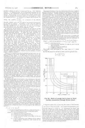
of physical contact will he much less than is the case where the curvatures are in the same direction, as happens when a concave touches a convex surface. The influence of the curvature of profiles in contact is illustrated in Figs. 22 and 23, which represent various positions of the profiles of the worm and wheel of Fig. 2r. the planes of section being symmetrically chosen with reference to the central plane. The contact along dl) in Fig. 22, though much less extended than that along &IT in Fig. 23, is of a kind much more adapted to withstand heavy pressures, the convex profile of the worm-wheel fitting into the concave profile of the worm in Fig. 22, whereas in Fig. 23 the opposite curvatures of the profile are less suited for retaining the oil-film upon which the power of sustaining a load depends. Generally speaking, on the side of the central plane where the worm is advancing the curvature of the profiles is alike though the path of contact is less extended, whilst on the side of the central plane where the worm is receding the contact path is more extended and the curvature of the profiles is unlike. It follows, therefore, that the mere extension of the contact surface of a worm and wormwheel is insufficient in itself to determine the amount of end pressure which can be safely sustained at any given speed, the curvatures of the various sections of the surfaces in contact playing an important part. The ability of any given worm-gear to withstand wear depends upon the maintenance of an oil or grease-film between the surfaces in contact. As the tooth of a worm-wheel passes through all the phases of its contact with the worm-thread, the line of contact traverses across its face, and is therefore continually passing across portions of the worm, which, since being in contact with the preceding worm-wheel tooth, should, in a well lubricated system, have been freshly lubricated. The rate of transference of the line of contact over the tooth face in conjunction with the tangential rubbing velocity is therefore a factor of prime importance. The width of the contact line or its dimensions across the face of the teeth and its effective breadth are factors of equal importance. By "effective breadth the dimension parallel to planes of section is meant, see Fig. 24. The "effective breadth " is indeterminable, but a comparative estimate can be formed of it by considering the curvature of the surfaces at any section, Thus, in Fig. 24 it is obvious that a much greater load would be sustained by a surface such as is illustrated at it than by surfaces such as L. In Appendix II. reasons will be given for taking the quantity A/ = as a measure of the effective breadth, where r, and t• are the radii of curvature of the surfaces
at the point of contact. According to this view the effective breadth is proportional to the square root of the product of the radii divided by the square root of their sum or difference according as the curvatures are opposite or alike.
In Appendix III an expression is given for this measure of the effective breadth when contact occurs at the pitch plane, and it is sufficiently near the truth to take this value as an average value for any particular section. A Table has been prepared (see Appendix IV), giving the values for the "effective breadth " of the sections of Figs. to, 20 and 2oa. Broadly speaking, the result of the calculations summarised in Appendix IV is that, for worm-wheel drives of similar general proportions as to height of teeth and arc of worm embraced by the worm-wheel fin transverse section), the average "effective breadth" of the contact line varies very slightly on account of variations in the ratio of thread pitch to diameter of worm. On the other hand, the effect of increase in diameter of the worm wheel has a markedly beneficial effect in this respect, the effective breadth varying as the square root of the diameter of the worm-wheel, The average width of the contact line across the face of the teeth will vary directly as the diameter of the worm, the slight diminution in width when the ratio of thread pitch to diameter is high being nearly balanced by the tendency towards greater "effective breadth."
Therefore, to sum up, the area of physical contact varies as the pitch diameter of the worm multiplied by the square root of the diameter of the wheel ; or, if the effects of varying the angle subtended by the pitch line of the worm-wheel at the centre of the worm be considered, it may be said that the effective area of contact varies as the continued product of the diameter a the worm, the tangent of half the angle subtended by the worm-wheel, and the square root of the diameter of the worm-wheel. At any instant the end pressure is shared between several teeth, and it is therefore justifiable to expect a greater power of sustaining loads as the number of teeth in action is greater. The variation in the number of teeth in gear is, however, much more apparent than real. Except in the case of abnormally small worm-wheels, the length of the contact paths on the worm-wheel side of the pitch plane is Unaffected by the size of the worm-wheel. On the other side, the contact lines most affected are those which are flattest, or which most nearly coincide with the pitch line. The actual variation in the number of teeth in gear at any one time is found on careful investigation to be small for widely differing sizes of worm-wheel. So that in comparison with other more important matters it may be neglected see Appendix V).
By keeping the ratio of the height to the thickness of the teeth as large as practicable, the greatest possible number of teeth are enabled to operate simultaneously. but at the same time, in order to avoid interference, the teeth should be pitched as finely as is compatible with strength and allowance for wear. It should be noticed that in respect of the height of the teeth the dictum given above is in direct opposition to the best practice with spur-gearing, where entirely different conditions are in force.
The effect of the angle of the worm thread remains for consideration. As the ratio of pitch to the diameter of worm becomes greater, the thrust of the worm is borne on a surface of greater inclination, and the actual pressure on the teeth is increased in the same ratio as the secant of the angular pitch. At the same time the width of the contact line across the face of the teeth is increased in the same ratio, so that the actual pressure per unit of width remains the same. It is not necessary therefore to take any account of the angle of the helix in making estimates of the "effective contact area." Under precisely similar conditions as to temperature, lubrication, nature of the surfaces in contact and rubbing velocities, it might reasonably be anticipated that the end thrust would be proportional to the effective area, and neglecting comparatively unimportant factors we may express the relation as follows
P=K.4./ D.dtan = some factor depending on conditions x effective breadth x effective width across the face of the worm-teeth. where P = safe end pressure in lbs.
d = diametor of worm at pitch line. D diameter of worm•wheel pitch line. fi = angle subtended by the worm-wheel at the axis of the worm.
If = a factor depending upon rubbing velocity, nature of the surfaces, temperature and nature of the lubricant, etc. Experience has shown that this relationship is far from simple irt practice, because of the great difference in the factor K imposed by variable conditions. Broadly speaking, what happens in the case of a worm-wheel drive is very much what happens in the case of a loaded journal. The action commences under certain conditions as to speed, temperature, and so forth, and as it proceeds heat is generated owing to frictional resistance, the amount depending upon the load, the lubricant, and the efficiency of the gear The temperature of the system rises until the heat generated by friction balances the heat lost by radiation and convection, when a stable set of conditions is established. But whilst the temperature is rising the lubricant is losing its viscosity, and though this tends to diminish the friction, and consequently the generation of heat, it nevertheless diminishes the power of sustaining a heavy load. A worm will therefore be successful if the viscosity of the lubricant does not diminish to such an extent that its load-sustaining properties are neutralised. If the surfaces be allowed to come into grinding contact further heating takes place, and the lubricant becomes still less viscous, and therefore incapable of bearing a load, and seizing will take place quickly.
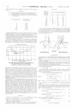
The question as to how much of the work done in rotating the worm is converted by friction into heat, can only be answered when the pressure, the velocity, the angular pitch, and the coefficient of friction between the surfaces, are all known.
Thus L = Lost work per minute = Peg Ir. -I41 (See Table 2,
— au page 28.)
where P = end thrust in lbs.
v = circumferential velocity of worm at pitch line in feet per minute.
a = tangent of angle of thread (s).
= coefficient of friction.
A diagram is given (Fig. 25) showing the values of the fraction for various values of IA and 0. The values to be ascribed to 1.4 are somewhat difficult to arrive at In experiments by Bach and Roser on a soft steel worm meshing with a bronze worm-wheel lubricated copiously with a heavy cylinder oil, /.4 calculated from the ratio of L to U varied from 0-067 to oozy, being generally speaking highest at low velocities (50 feet per minute) or at high velocities (over 1000 feet per minute) ; whilst at medium velocities (27o-55o feet per minute) it was lowest, varying little (won to 0-027) under widely differing loads. In some experiments made by Sellers and Co. on cast-iron surfaces the coefficient was highest at very low velocities (3 feet per minute), and gradually got less as the velocity increased up to zoo feet per minute. In these experiments the value of a varied but little for varying values of pressure. Values of a deduced from Bach and loser's experiments are given in the accompanying diagram (Fig. 26).
The advantage of employing worms with as large a thread angle as possible, that is to say, with the greatest possible ratio of pitch to diameter, now becomes apparent. For a given amount of work to be performed, by doubling the pitch the velocity is halved and the work wasted in heat is materially reduced. The effect is two-fold : the temperature of the lubrieant being less, its viscosity is sustained ; and the velocity being less the value of the load that may safely be borne is increased. Such experiments as have been made to determine the relationship between the pressure and velocity are not altogether concordant, and it remains to establish firmly the laws which govern this sort of friction. The most careful experiments known to the author were those on a soft steel worm-gearing. with a bronze worm-wheel, with oil-bath lubrication, made by C. Bach and loser, alluded to above. The lubricant was a very thick cylinder-oil, and the experiments were continued until there was no further rise of temperature, the heat lost through radiation balancing the amount generated in friction.
The values of K in the appended Table have been calculated from the experiments. If the values of P are calculated by means of the values of K here given, it must not be assumed that they are the highest values that could be safely adopted, but they represent the pressures which may be adopted for continuous running with limited rise in temperature. it must be pointed out, however, that they are only reliable if the conditions of the original experiments are carried out. These were as follows : the lubricant used was a viscous cylinder-oil and the surfaces soft steel and bronze, the worm dipped into an oil-box whose volume was about three times that of the worm, and the worm-wheel was enclosed. It will readily be seen, therefore, that with superior methods of cooling and by the choice of superior working surfaces, very much larger working pressures might be realised, especially if the worm be of hardened steel.
TABLE 2.
Values of K in formula P = K V D. tan 2 deduced from the
experiments of Bach and Rosen The ccnditions being Maierial.—Soft steel worm. Bronze worm-wheel. Llibricant.—Heavy cylinder-oil.
.latbeication.—Worm dipping in oil bath. Size of bath about three times volume of worm with proportionate cooling surface. The experiments of Messrs. Sellers alluded to above showed that for short periods the value of K for velocities up to zoo feet per minute might be as high as 320 in the case of cast-iron surfaces lubricated with lard oil. For continuous running, however, much lower values should be taken.
. Let OX, Fig. 27, represent the axis of a screw or worm, and OP the generator of one of its acting surfaces, both being in the vertical plane.
The intersection of OP and the axis OX at 0 is chosen as the origin of co-ordinates. The worm surface is generated by the generator simultaneously advancing along and rotating about the axis OX; an advance of IN units corresponds to one complete revolution. Let a be the advance of the generator along OX when the latter is turned through art angle U.
Then a-t.12 •-• (1) When the generator rotates through an angle p it moves from the position OP to 02Pi (see side elevation, Fig. 27) or from 01 F' (see end elevation). Then it is easily seen from the figure that sin t= (3e21-z9-1 (2)
The expression (5) is the equation of the generated .helical surface.
In order to obtain the equation of the curve of intersection of such a surface by a plane parallel to the axis and distant if from it and from the initial position OP of the generator, we have only to put 4.= t in (5) and we get