


A NOVEL CHANGE-SPEED MECHANISM.
Page 30
If you've noticed an error in this article please click here to report it so we can fix it.
A Resume of Recently Published Patent Specifications.
HE,Y a mischance two illustration blocks became changed
as the issue of The Commercial Motor for last Tuesday was going to press, and a block which had been prepared to illustrate our description of M. Esnault-Pelterie's invention was inserted with the matter describing Messrs. S. and E. G. Russell's bonnet fastener. There is now no need to illustrate the latter device, as our remarks sufficiently described it. This will explain a second appearance in this page of the illustration published last week, as it is required in order to make clear a very ingenious form of friction
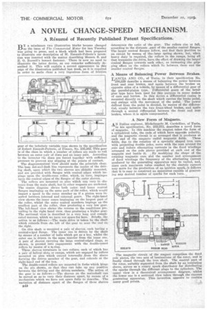
gear of the infinitely variable type shown in the specification of Robert Esnault-Pelterie, of France, No. 235,562. This gear is of the class in which a number of rollers are made to roll between an outer Fair of discs and an inner pair. According to the inventor the discs are forced together with sufficient pressure to prevent any slipping at the points of contact.
The diagrammatical view should make the principle clear. The base dot-and-dash line represents the centre of the driving shaft, upon which the two sleeves are slidably mounted, and are provided with flanges with conical edges which impinge upon the double-cone roller, which, in turn, impinges upon the conical edges of the flanges of the outer sleeves.
The rollers are mounted in pins which can vary in distance from the main shaft, but in other respects are anchored. The centre diagram shows both outer and inner conical flanges impinging on the same path of the roller, which would impart a speed to the outer member as if a pinion were inserted between internal and external gears. The right-hand view shows the inner cones impinging on the largest part of the roller, whilst the outer conical members impinge on the smallest part of the roller, thus producing a very low gear. The left-hand view shows the reverse to the conditions prevailing in the right hand view, thus producing a higher gear. The sectional view is described in a very long and complicated manner, which we have not space for here. Briefly, the action is as follows :—The main drive is taken by the shaft which extends from the left of the gear to near the end on the right.
On this shaft ,s mounted a pair of sleeves, each having a conical-eiged flange. The inner one is driven by the shaft by Means of a number of balls which act as a key, whilst the outer one is driven in the same manlier from the inner one. A pair of sleeves carrying the large conical-edged rings, as shown, is pressed into engagement with the double-coned rollers by means of 'a siring.
These sleeves terminate in two collars; each of which has a pair of helical slots or ramps, which are engaged by rollers mounted on pins which extend internally from the sleeve forming the driven member of the gear, and extends at the right-haul end of the box. '
The double-coned rollers are mounted in forks which hinge on the pin shown, so that they can take up any position between the driving and the driven members. The action of the gear is as follows :—The sleeves on the mainshaft can be moved so as to vary their distance apart, by means of a mechanism which we have not space fully to describe. The varia,tion of distance apart of the flanges of these sleeves 844 determines the iatio of the gear. The rollers rise or fall, according to the distance ,part of the smaller conical flanges. The larger conical flanges follow, and find their position to an extent by means of the.large spring shown, but, when heavy duty is required, the rollers in the ramps, being all that transmits the drive, have the effect of drawing the larger conical flanges towards each other, so increasing the gripping effect on the rollers which lie between. them and the smaller conical flanges.
A Means of Balancing Power Between Brakes.
LANCIA AND CO., of Turin, in their specification No. 236,239 describe a means of balancing the power between front and rear brakes, and again between the brakes on opposite sides of a vehicle, by means of a differential gear of the parallel-pinion type. Differential gears of the bevelgear type have been used for this purpose in many makes of cars and lorries. In this device a differential casing is mounted directly on the shaft which carries the brake pedal, and swings with the movement of the pedal. The power (leaved from the pedal is divided, by means of the differential, evenly between the two front-wheel brakes, and again through a second differential between the front and rear brakes, where it is again compensated. •
A New Form of Magneto.
AN Italian engineer, Michelangelo M. Cardellino, of Turin, in his specification, No. 232,573, describes a novel form of magneto. In this machine the magnet takes the form of a cylindrical tube, the ends of which have opposite polarity, and the magnetic circuit is so arranged that it produces at each end of the magneto radial magnetic fields. These fields, due to the rotation of a specially shaped iron core with projecting double poles, move with the core around its Axis and induce alternating currents in the fixed windings arranged on the pole pieces provided at each end of the magneto and inside it. By modifying the shape of the rotating magnetic core and the number and arrangement of fixed windings the frequency of the alternating current produced by the generating apparatus may be varied, and, since each maximum value• reached by the electric current may serve for the production of an ignition spark,,it follows that it is easy to construct an apparatus capable of generating any desired number of sparks for each turn.
The magnetic circuit of the magnet comprises the fixed pole pieces, the two sets of laminations of the rotor, and is finally closed through the iron shaft. The central part of the rotor, suitably separated from the shaft by an insulating sleeve, serves as a rotary spark distributor for distributing the sparks through the different plugs to the cylinders. The upper view is a theoretical arrangement diagram, whilst the lower one is a sectional view taken through the current generating apparatus. This invention appears to contain many good points.