


Eom Drivers &Mechanics
Page 19
If you've noticed an error in this article please click here to report it so we can fix it.
TEN SHILLINGS WEEKLY is paid for the best communication received, and 'me penny a line of ten words for anything else published, with an allowance for photographs.
Send us an account of any shecial incident of your work or experience. If suitable, we will edit your notes, supply a sketch when required, and pay you for everything published. Mention your employer's name, in confidence, as evidence of good faith. Address to The Editor, THE COMMERCIAL MOTOR, Rosebery Avenue, London, E.C.
Light Up Your Lamps At--„ 8.5 on Thursday ; 8.6 on Friday ; 8.7 On Satiirday ; 8.11 on Monday ; 8.13 on Tuesday ; 8.14 on Wednesday.
Engine Overhaul.
[1620] "T.P." (Holborn) writes :—" In a great many businesses a lull follows the Easter rush, and this is frequently taken advantage of, and an overhaul made of the motorvan. Under such circumstances the following hints may not be altogether unacceptable. It is usual to start with the engine, this being the principal component, and it is advisable first of all to take off the radiator, not forgetting to empty it The radiator removed, the engine is much more accessible than ordinarily. Probably the next thing to be done would be to remove the cylinders ; this of course, after the smaller items, such as carburetter, magneto, water pipes, have been detached. When lifting the cylinder casting, be careful to see that the pistons are not allowed to fall ; there is great danger of their being cracked in that event. Whenremoving the piston rings, three pieces of thin steel, such as broken hack-saw blades, are of great assistance. They should be pushed behind the rings, and then the latter slid off over them.
"The valves will probably require some attention. If, as is possible, the faces are grooved, it will be necessary to re-turn them in a lathe. This is comparatively a simple job, and can be done with a smooth file held at the correct angle whilst the valve is revolving at a fairly high speed. They will, of course, afterwards require to be ground in in the ordinary way. During the grinding-in process it is advisable occasionally to lift the valve and then turn it to a fresh position. This prevents grooving the seats. "When washing down the engine use clean paraffin. There is less likelihood of grit getting into the bearings. If there is a considerable amount of up-anddown play in the big-ends, end play does not matter to the same extent ; it will be advisable to call in the aid of a skilled mechanic as the taking up of any considerable amountof sah play is not an amateuies job. When replacing the connecting rods, see that all the bolts are tight and the split pins are replaced. The gudgeon-pin fastening calls for similar attention. I have known several serious accidents as the result of neglect of this point.
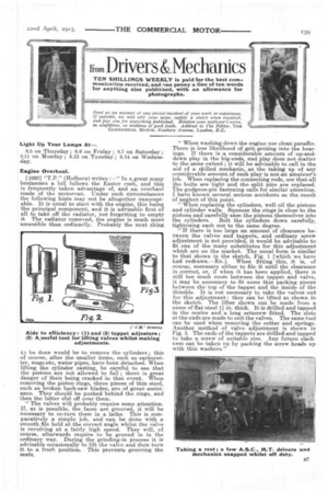
"When replacing the cylinders, well oil the pistons and cylinder walls. Squeeze the rings in close to the pistons and carefully ease the pistons themselves into the cylinders. Bolt the cylinders down carefully, tightening each nut to the same degree. "If there is too large an amount of clearance between the valves and tappets, and ordinary screw adjustment is not provided, it would be advisable to fit one of the many substitutes for this adjustment which are on the market. The usual form is similar to that shown in the sketch, Fig. 1 [which we have had redrawn.—En.]. When fitting this, it is, .of course, necessary either to file it until the clearance is correct, or, if when it has been applied, there is still too much room between the tappet and valve, it may be necessary to fit some thin packing pieces between the top of the tappet and the inside of the thimble. It is not necessary to take the valves out for this adjustment : they can be lifted as shown in the sketch. The lifter shown can be made from a niece of flat steel 1.1 in. thick. It is drilled and tapped in the centre and a long setscrew fitted. The slots at the ends are made to suit the valves. The same tool can be used when removing the cotter and springs. Another method of valve adjustment is shown in Fig. 3. The ends of the tappets are drilled and tapped to take a screw of suitable size. Any future slackness can be taken up by packing the screw heads up with thin washers."