


• HINTS ON MAINTENANCE.
Page 28
Page 29
If you've noticed an error in this article please click here to report it so we can fix it.
How to Get the Best Out of a Vehicle, to Secure Reliability and to Avoid Trouble.
ONTRIBUTIONS are invited for this page • from fleetmanagers, drivers, garage foremen,
and mechanics, works staff and draughtsmen, and will be paid for on a generous scale. Every system, make, and type of 'commercial motor vehicle will be dealt with, and the matter should be written with a view to the disclosure of workshop and garage practice in the maintenance of a vehicle—practices
which., whilst they may be quite normal, are Peculiar to the particular vehicle and -maY, not be 'generally known to those responsible for its running. Expedients and suggestions for overcoming roadside and other troubles are covered in the following page, dealing with letters from our driver and mechanic readers. Communications should be addressed to " The Editor, The Commercial Moteir; 7-15, RoseberY Avenue, London, E.C.1."
294. —Some Suggestions for Improving the J-type Thornycroft.
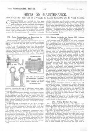
The three sketches which we reproduce show several interesting and useful little improvements which can easily be carried out on the J-type Thornycroft vehicle.
One is an oil-retaining gland for the gearbox selector rods. This requires very little explanation, as its construction can clearly be seen from the illustration, and onceit is fitted it will last for a considerable time without. any attention, and then only requires the fitting of a new felt washer. This gland entirely, prevents the loss Of lubricant, which sometimes becomes serious when the selector rodkbushes are much worn.
The second illustration shows a useful improvement to the selector rod drop arm. This is held in position in the ordinary way by a key and cotter bolt, the last-named just entering the shaft. With this fastening there is a great tendency for the drop arm to work loose, with the result that it prevents full engagement of the gears, increasing the wear, and making changing difficult.
If the drop arm be removed and a 3-32-in, slot cut from the shaft hole some distance down the arm, this allows a certain amount of spring, and when the cotter bolt is tightened up the drop arm clamps on to the shaft
A trouble , which is sometimes experienced with Thornycroft and other springs is loosening of the spring holding-down bolts. The; Thornycroft method of overcoming this difficulty is by the use of a special spring plate placed under the spring and giving a two-line bearing. Our contributor suggests that the top spring plate should he machined off to give a similar bearing, so that, however much the springs are flexed, no extra stress is put on the bolts.
B44
295.—Simple Methods for Curing Oil Leakage from Engines.
Oil leakage from the engine is not only annoying from the point of view that the engine is always in a dirty condition, but it is unsatisfactory because of the loss of expensive lubricant, and there is also a danger of the oil level in the crankcase falling below the margin of -safety. Most leakages are due to very simple causes, which can be cured by a little careful attention. Oil escapes from the crankshaft bearings, front.or rear, are often merely the result of dirt blocking the oilreturn ways, orl possibly, if a paper packing be used at this point, it may have slipped during the reassembly of the parts and be coveting one orother of the oil-returns. In the case of oil oozing from a face joint, the cause may. be a tiny particle of grit, swarf, etc., -which may be holding the -faces apart, although ,externally the joint may look quite satiifactory. In any. case, paper joints are somewhat delicate, and they may easily become torn between the faces, or the paper may become crumpled and thus form a double thickness at one part.. , Where studs or setscrews are employed, especially in aluminium or brass, burrs may be drawn up from the face around the stud holm These prevent opposing faces from jointing correctly.Therefore it is essential that the eurresponding holes. of such 'joints should be given a slight countersink or radius in order to accommodate any burrs which may be present or arise. Gold size is a satisfactory oil-tight medium to use on a joint either alone or in conjunction with a paper washer.
Oil leakage sometimes occurs at the unions of external oil pipes. Examination usually discloses one of three causes. The pipe itself may be found split, the solder or brazing around the-union nipple may be cracked or otherwise faulty, or, possibly, the pipe is not bent or set correctly, so that if a conical 'nipple is 'employed this does not fit snugly into its socket, or if the joint be of the flanged type, it may not butt up squarely. •
Oozing of oil often occurs from ail pressure indicators, especially those of the plunger type. This usually indicates the need for renewal of the leather washer fitted to the plunger.
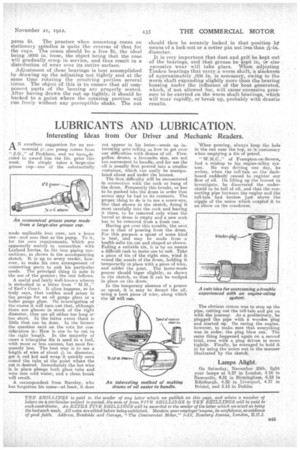
296.—Fitting Timken Bearings.
When fitting Timken bearings, the utmost care should be taken to ensure that the wear will be evenly distributed over the entiresurface of the' cups an cones. In cases where the cups revolve, as in front and rear wheels, the wear on them is automatically, distributed by their own rotation.
The press fit of the cups is very important, as, with carelessness in fitting, trouble develops 'much more rapidly with the cups than with. any other component part of the bearing. The reason for the press fit being so important is that the stros.ses in the cups are generally tensile in 'character, and, consequently, have a tendency to expand the cups. This expansion is best resisted by mounting the cups with press fit. The practice when mounting cones on stationary spindles is quite the reverse of that for the cups. The cones should be a free fit, the ideal being .0005 in. loose, the object being that the cone will gradually creep in service, and thus resultin a distributiOn of wear over its entire surface.
Adjustment of these bearings is hest accomplished by drawing up the adjusting nut tightly and at the same time rotating the revolving portion several times. The object of this is to, ensure that all component parts of the bearing are properly seated. After having drawn the nut up tightly, it should be backed to a point where the rotating portion will run freely without any perceptible shake. The nut
should then be securely locked in that position by means of a lock-nut or a cotter pin not less than . diameter.
It is very important that dust and grit be kept out of the bearings, and that grease be kept in or else excessive wear will take place. When adjusting Timken bearings that carry a worm shaft, a slaAness of approximately ,005 in. is necessary, owing to the worm shaft expanding slightly more than the bearing housing under the influence of the heat generated, which, if not allowed for, will cause.excessive pressure to be exerted on the worm shaft bearings, which will wear rapidly, or break up, probably with drastic results.