


A DOUBLE-DECKED BUS WITH SEPARATE EXIT.
Page 74
If you've noticed an error in this article please click here to report it so we can fix it.
A R4sume of Recently Published Patent Specifications.
THEprovision for a continuous stream of passengers, entering and leaving at the same time, has, for some time, been recognized by many as the correct way in which a bus should be constructed, so we are not surprised to see that inventors are turning their attention to the design of bus bodies constructed on these lines. With the design
of bus body as used to-day there is an appreciable amount of time lost at many stooping places through those who wish to enter having to wait until all those who wish to leave the bus have had time to do so. In many cases, the stream of incoming passengers has actually to halt and get out to enable some sleepy passenger, who has just discovered that he has arrived at his destination, to leave the bus.
The present invention, patent No. 270,892, H. L. Watson, is intended to relieve this congestion by providing separate doorways for entering and leaving for both lower and upper decks. Two double folding doors are provided near the front of the bus for exit purposes, whilst the usual entrances are maintained at the rear. The stairway leading to the upper deck is described as being movable, so that when required it can be removed and replaced by additional seating accommodation.
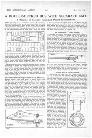
A Combined Stabilizing Rod and Shock Absorber.
MANY efforts have been made to relieve front axles from the strains imposed upon them by the torque resulting from the application of brakes to front wheels. The specification of G. C. Capps., of Turin, No. 270,190, describes the fitting of a radius rod, and an upstanding arm from the axle, which forms an articulated parallelogram. By this means the springs are relieved from all strains such as those shown in an exaggerated form by dotted lines. According to the specification, the enlarged boss, which forms the fulcrum of the radius rod, may act as a shock absorber or damper, as it is referred to as a frictional device of known type. No claim is made for this part of the arrangement.
The argument set forth in the specification mentions the fact that the front axle is subjected to torsional and flexotorsional stresses, owing to the brakes having a tendency to follow the revolving wheel and that the axle is sunk below the wheel axis. This is true, but we do not see how the present invention helps matters. The part of an axle that is subjected to such stresses is that which lies between the spring or other means of anchorage (such as a radius rod) and the steering head. As the radius rod described
in this specification is fitted close to the spring we can hardly see how it can relieve from stress that part of the axle which lies between it and the steering head. It would seem that the yielding anchorage which the spring affords would be more likely to minimize the stress than the more rigid anchorage of a radius rod.
An Automatic Trailer Brake.
A BRAKE for trailers which acts automatically whenever the trailer overruns, or closes up on its tractor, is described by Johann Sehlagenhauf, of Zurich, in his specification No. 268,661. A cross-shaft is fitted to the trailer and forms the base of the triangle of the pull bar. This shaft is mounted in bearinga and has a short lever, or crank, keyed to it at each end, to which the rear ends of the draw-bar are pivoted. In the centre of the shaft is keyed a third lever or crank, to which is attached a cable working the brakes of the trailer by moans of the link and lever shown. In operation, when the trailer closes up on the tractor the draw-bar acts as a push-rod and imparts a rotary movement to the cross-shaft by means of the cranks, in the direction of the arrow, and, through the central crank and its
link anti cable, applies the brake to the trailer. Mention is made of a hydraulic dashpot shock absorber mounted on the cross-shaft, which is intended, to relieve the device from sudden shocks due to the retarding of the tractor causing a too abrupt stoppage of the trailer.
Cleaner Air in the Cylinders.
ALTHOUGH our roads are now comparatively dustless, and we have not the need for air filters that exists in more dusty conditions, we must not forget that all vehicles that are made in this country are not essentially intended for home use. Even for use on dustless roads, there must be a certain amount oi grit always Boating in the air, and great care is taken to exclude it from every part excepting those which are the most vital of all—the cylinder walls.
Some contend that such dust as we get in this country Is harmless ; yet we know that it forms a very appreciab'e proportion of the so-called carbon deposit found in cylinders. We also know that cylinders require periodical regrinding and the fitting of new oversized pistons. Surely the exclusiGn of dust should minimize the formation of carbon and the wear of cylinders, and would be worth while so long as it can be accomplished by simple means.
The specification of R. D. Watrous, of Illinois, U.S.A., No. 270,970, shows a simple form of air cleaner in which there are no working parts. The inlet pipe through which air passes on its way to the eatburetter is upturned at its end, and is arranged so that it supports a hood by means of four arms. Attached to the pipe is a disc which is notched, and each arm twisted so that it imparts to the inrushing air a swirling movement. This has the effect of throwing all particles of dust, which are heavier than air, to the walls of the hood, from which they fall dear.