


AN INTERESTING SILENCER:
Page 38
If you've noticed an error in this article please click here to report it so we can fix it.
A Résumé of Recently Published Patents.
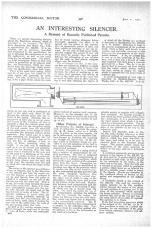
There are severed interesting features about the Blackburn silencer, which is described by the patentees, The Blackburn Aeroplane and Motor Co., Ltd., in specification No. 162,934. It is applicable, and is, moreover, described and illustrated in the specification, for use in silencing the aspirations of air by the carburetter, as well as the noise made by the exhaust gases. The following brief description refers to that type which is preferable SB an exhatst muffler; our -illustrations, which are reproduced from the drawings which accompany the specification, show both types.
There is the usual outer casing, which may be of any form, but which for obvious reason will generally be cylindrical. The inlet, as shown on the drawing, is.by a pipe which enters the main
easing at one end, and is prolonged almost to the other end, where it discharges the exhaust gases into the interior of the casing Actually, this• arrangement of inlet pipe is not an eesential feature of the invention, all that is required is that the exhaust gases shall be discharged into the elongated casing at the end remote from the extremity of the outlet pipe, in the design of which is embodied the principal feature of•the invention. This outlet pipe is a plain tube extending for practically the full length of the silencer. It is open at its end, but has, in addition, a hole, or series of holes, extending along its length. If one hole only is employed, • such as is; to all intents and purposes, shown irs the drawing, then the hole tapers from a maximum at the open end of the tube to a minimum at its other end. If a number of holes is preferred, then they diminish in size likewise, the largest being situate near the open end of the tube, the smallest near the end at, which the tube enters the body of the silencer.
The action of the silencer is as follows: When an impulse, due to the liberation of the exhaust gas from the engine enters the silencer, a wave of pressure is set up and travels from the point at which it is released, at one end of the silencer towards the other end. That is to say, it travels along towards the open end of the outlet tube. Some of it, however, immediately escapes into the outlet tube through the small end of the tapered hole or series of holes. The remainder continues to travel along the eileneer, being gradually relieved by escaping into the ever-widening slot or series of holes, until, *hen it reaches the orren end of the•outlet tube, the bulk of the gas escapes along that tube. As part of the impulse escapes immediately through the small end of the slot or series of holes, while the remainder B40 has to travel varying distances before eventually escaping, the effect is to spread out the sound of the impulse over an appreciable period of time, and thus reduce its intensity at any one instant. In the case of high-speed multicylinder engines this period of time will most likely be greater than the period between the exhausting of one cylinder and the next, so that almost complete silence may be obtained.
The advantages are that. as the silencer does not depend on baffling to obtain silence, the passages may be large, thus redncing back Dressure to a minimum. Further, the effect of sooting-up is not to cause back pressure, but merely to close up the small end of the. taper slot or series of boles, thus in effect shortening it and only redtteing the degree of silence instead of causing back pressure. Moreover, as the passages are, in the main larger than is usual in the majority of silencers, there is less liability to soot up at all.
Other Patents of Interest.
Specificetion No. 162,956 describes a form of carburetter to which the patentee, A. E. Jones, refers as a bubble type, in which, as the name implies, the ansis earburetted, and an explosive mixture formed by bubbling the incoming air through the liquid fuel. In the design which is described, means are provided to prevent splashing of the fuel in the carburetting chamber to arrest any unvaporized particles. Actually, it consists of a casing divided into a number of compartments by ver. tics] partitions. The fuel is contained in the largest of these compartments, in which there is a sloping partition, which divides the upper portion of the compartment from the lower. Connection between the two portions is established by serrating one edge of the partition where it touches the side of the compartment. so that earbtiretted air may pass through the many triangular apertures thus formed. Air enters by a vertical pipe, the upper end of which is open to the atmosphere, while the lower end is close to the bottom of the fuel tank. Connection between each compartment and the next, is by means of an inverted U pipe, of which one leg is shorter than the other. The short leg enters the top of one compartment, carrying the mixture on its way towards the engine, the longer leg delivers it into the next chamber, where any liquid fuel is deposited,
to be subsequently removed. The U tube leading from the final compartment is coupled to the induction pipe. Provision is made for guarding against risk of explosion or fire in the carburetter as the result of a backfire.
A detail ef the Parker gas producer is described in Specification No. 162,899, by J. W. Parker. Reference is made to the general arrangement of the producer itself, which is fairly well known to our readers, and particular attention is then drawn to the arrangement of the watercooled &dears. A fin, or several fins, is cast on to the underside of the fire. bars, am] it.dips into a trough of water kept supplied with fluid from a reservoir governed by a float. The fin is so designed that it prevents ash from falling into the water, which, besides cooling the bars, serves to supply the vapour which is essential for the preparation of producer gees A novelarrangement of inlet pipe is described by Sheffield-Simplex Motor Works, Ltd., in No. 162,758. It is ap
plicable mainly to engines with independent cylinders. An annular passage is cast round the lower portion of the cylinder; practically, it is a continuation of the water jacket, from which it is sepa rated by a horizontal partition. The gas enters' at one side and passes round both sides of the cylinder on its way to the induction pipe.
Ruston and Hornsby, Ltd., in No. 162,749, make further reference to their patented method of constructing steam boilers, which ha' been described on this page, and which is to be seen in concrete form in the Raneome steam wagon. The present patent covers the application of the same principle to boilers of the type used -on a Yorkshire wagon. A combined pneumatic and spring suspension is the subject of No. 158,551, by A. Joel and Co. A quarter-elliptic spring is pivoted at both ends: at the butt end to the extremity of the frame, at the other end to the axle. Near the butt end a bracket is secured, which is coupled to a piston, which bears on an inflated lining of a suitable vessel, which is bolted to the chassis. Shocks are absorbed by the combined effects of flexion of the spring and compression of the inflated A hydraulic clutch is the subject of No. 162,7'76. The port for ensnring a replete cylinder is, in this machine, drilled through the centre of the piston rod and emerges in a groove cut in the strap of the eccentric which operates the pump cylinder. Release of pressure between the end of the rod and fuse of the strap allows oil to enter if required. The patentee is A. Coats. In the fuel generating apparatus which is the subject of No. 162;861, by H. F. flee, provision is made, • in a.petrol carburetter, for the utilization of the gases from heated ammonia, creosote, 'and (Achim carbide.