


For DRIVERS MECHANICS & FOREMEN.
Page 21
If you've noticed an error in this article please click here to report it so we can fix it.
A PRIZE OF TEN SHILLINGS is awarded each week to the tender of the best letter -which, we publish on this page ; all others are paid for at the rate of a penny a line, with an allowance for photographs. All notes are edited before being published. Mention pour employer's name, in confidence, as evidence of 400d faith, Addres,s, p., 31..cind P., "The Commercial Motor," 7-15, Rosebery Avenue, London, P.C. 1.
Lamps Alight—
Light your lamps at 5.58 in London, 6.3 in Edinburgh, 6.1 in Newcastle, 6.7 in Liverpool, 6.4 in Birmingham, 6.8 in Bristol, and 6.51 in Dublin.
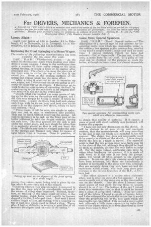
Improving the Front Springing of a Steam Wagon.
The sender of the following coninfunicatiao has been. awarded the 108. prize this week..
[1831] "W.A.B." (Whittlesford) writes :—" As the result of observations made when looking over other drivers' steam wagons, I came to the conclusion that quite a number of them suffer owing to 'the front spring, settling, or losing a little of its camber after prolonged use. The effect is to cause the pivot pin of the front axle to strike the top of the slot in the swivel jaw. Wear on the bearing surfaces of the spring and slipper block has the same effect.
"After a time it occurred to me to examine my own wagon, and I discovered that it was going in precisely the same way as the others. I thereupon set to work to devise some means of oorrecting the fault, by endeavouring to lift the axle back to its original position relative to the slot, in the swivel jaw.
"Clearly what was wanted was some means of taking up for the wear on the springs and slippers, and I did this very simply by fitting a couple of liners between them. I made the liner..s from half-inch plates, each 3 ins, wide by 6 ins, long, and bent over at the ends to fit on the slippers [See sketch, which we have had redrawn.—ED.]
" These liners, it will be seen, are simple to make: they are just as easy to manoeuvre into. position. They can be fixed without removing the spring. All that is necessary is to jack up the front part of the boiler sufficient to take the weight entirely, leaving the axle free. The best position for the jack is just under the swivel plate, and care should be taken that it is centrally placed so that it will not bend this plate. The liners may then be wedged under the ends of the springs and trapped into place by means of light blows from a hammer. Once in position, of course, they cannot move, being held in place by the lips which fit over each end of the slipper.
r Having effected this improvement, it occurred to me that the wear might be considerably reduced if the means of oiling were improved. Instead, therefore, of trusting to the usual small oil holes in the spring plates, which holes tend rapidly to become clogged with dirt, I enlarged them. Into each I fitted a short length of in. gas tubing, with a coupling on top of each into which could be fitted a-pIug. Thereafter I had no difficulty in keeping a good film of oil between the slipper and the ends of the spring."
Some More Special .Spanners.
[1832] "H. S.H." (Wood Green)i 'writes :—" The description of a special type of box spanner for unserewing ea,stle nuts which are inaccessible either to the ordinary box spanner or the common key, recalled to my mind a couple which I made and used for some time. I enclose sketches [which we have had redrawn.—En] of these tools. The top one, it will be seen, is made from flat bar steel. If a piece of tool steel can be obtained for the purpose so much the better, although in these times it is almost impossible
to obtain that quality of material. If it cannot, a piece of good mild steel, suitably case hardened, will answer the purpose.
"I have not put any dimensions on the sketch. It will be obvious to all your driver and mechanic readers, that the measurements will vary according to the size of nut for which it is intended to use the spanner. The shape, too, does not neceSsarily. need to be exactly as shown on the sketch. I have simply drawn the tool as I made it myself. The essential point is that the two prongs must be a fairly easy fit in the slots of the nut, although they should be kept as thick as possible, as they are very liable to snap off. For the same reason, particular care must he taken when haidening the spanner, if it is made of mild steel, as if the case is too deep the prongs, again, will break off when, subject to the slightest pressure. In pre-war days this warning would hardly have been necessary,. but there are undoubtedly a number of mechanics in the shops now who, although they are certainly doing very well, have not had the experience Which others, who have long since gone overseas in the various branches of the YET., A. S.C., have had.
"The other spanner is a rather more elaborate affair, and is after the style of a box spanner. I procured a castle nut of the same size as the inaccessible one on the chassis. Into the slots I brazed some small pieces of tool steel, leaving these to project about in. or -& in. The bottom Of the nut I turned down to a convenient size so that it could be brazed into a piece of scrap steel tubing. Near the other end of the tubing I bored a couple of tomrny holes, and I also enlarged the hole in the nut so that it would clear the projecting end of the bolt upon which the inaccessible nut was fitted. This proved a most useful tool, although a little more expensive to make than some of the others which have been described in these pages from time to time."