


Two New M.A.N.
Page 35
If you've noticed an error in this article please click here to report it so we can fix it.
Oil Engines
WITH its long experience of oil engines the M.A.N. Co., of Nuremberg and Augsburg, strictly adheres to the six-cylindered unit on the ground that it is more flexible and works more smoothly than four-cylindered and three-cylindered engines. The smaller bore of the sixcylindered engine, with a relatively small piston displacement, involves considerable difficulties regarding the accommodation of sufficiently large valves and the injection nozzles. Additionally, as is well known, the correct metering of the fuel to small-displacement cylinders remains a big problem, and it is still practically impossible to attain the same economical fud consumption on such engines as with units having cylinders of larger piston displacement.
Power Outputs of 70 b.h.p. and 80-90 b.h.p.
The M.A.N. Co. has, nevertheless, tackled the problem and, it appears, with success. It has just introduced two new six-eylindered engines of 70 b.h.p..and 804)0 b.h.p. respectively, both having a bore of 105 mm. (4.133 ins.). The smaller of the two engines has a stroke of 130 mm. (5.118 ins.), the other of 140 mm. (5.511 ins.), so the respective piston displacements are 0.700 litres (408 cubic ins.) and 7.300 litres (445 cubic ins.). Thus the engines do not differ greatly in size or output. .
The above-mentioned power outputs are attained with an engine speed of 1,800 r.p.m., involving piston velocities in the one case of 25.59-ft. per sec., and in the other (due to the longer stroke) of 27.56 ft. per sec.
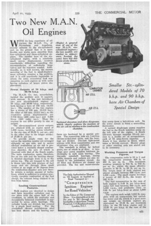
To provide ample room for the valves the injection nozzles are arranged obliquely on one side, and to secure efficient combustion an air cell is provided below a conically shaped combustion chamber, the axis of which is identical with that of the Bosch nozzle. The main combustion space, therefore, lies on one side and the burning charge is directed slautingly from it on to the piston top. The air trapped in the cell is blown into this rich mixture of fuel spray and air through three small orifices at an angle of 30 degrees from the combustion-diamber axis and thereby secures a certain amount of turbulence, which is sufficient to produce practically complete combustion of the fuel charge, the exhaust being claimed to be free from fumes.
Leading Constructional Features.
Both engines are identical in design and have monobloc cylinders cast in one piece with the upper half of the crankcase, in which the statically and dynamically balanced crankshaft is supported by seven plain bearings. The cylinder heads are divided, but covered
by a single hood casting. For the crankshaft chrome molybdenum steel has been chosen and the bearing sur
faces are hardened by a special process. The connecting rods are I-section chrome-nickel-steel units, and the bearings are divided. Die-cast light-metal pistons with three compression and one oil-scraper ring are employed.
The camshaft is driven by helical gears, one of which is of fibre. A twostage gear pump supplies lubricant individually to each main bearing. The big-ends, camshaft bearings, timing gears, tappets and rockers are also included in the lubrication circuit. An oil filter and Elektron air cleaner are provided. The fan and water-circula tion pump form a belt-driven unit. In the water circuit is fitted a controlling thermostat.
A normal diaphragm pump supplies the fuel to the Bosch injection pump on the left side of the engine. A Bosch 130-watt dynamo supplies 12-volt current to a double set of accumulators,
each of 75 amp.-hours capacity. A Bosch 4 h.p. starter is fitted, which takes a 24-volt current. Heater plugs or other starting aids are stated not to be necessary.
Working Pressures and Torque Figures.
The compression ratio is 15 to 1 and the compression pressure 426 lb. to 455 lb. per sq. in. The maximum working pressure is 711 lb. to 782 lb. per sq. in., whilst the mean effective pressure is 80 lb. to 85 lb. per sq. in. The torque lines of both engines are almost straight between 600 r.p.m. and 1,800 r.p.m. The small engine develops a torque of 217 ft.-lb., the larger of 246 ft.-lb.
The fuel consumption in the case of both engines is 0.44 lb. per b.h.p.-hour under full load between 900 r.p.m. and 1,300 r.p.m., and gradually rises to 0.48 lb. per b.h.p.-hour at about 1,800 r.p.m.
The engines each weigh 1,212 lb. complete with all components, but excluding water and oil, which is a good average weight as Cerman engines go, equivalent to 17.35 lb. per maximum b.h.p. in the 70 b.h.p. engine and to 13.45 lb. per b.h.p. in the ease of the larger engine.