 1
1 2
2 3
3 4
4 5
5 6
6 7
7 8
8 9
9 10
10 11
11 12
12 13
13 14
14 15
15 16
16 17
17 18
18 19
19 20
20 21
21 22
22 23
23 24
24 25
25 26
26 27
27 28
28 29
29 30
30 31
31 32
32 33
33 34
34 35
35 36
36 37
37 38
38 39
39 40
40 41
41 42
42 43
43 44
44 45
45 46
46 47
47 48
48 49
49 50
50 51
51 52
52 53
53 54
54 55
55 56
56 57
57 58
58 59
59 60
60 61
61 62
62 63
63 64
64 65
65 66
66 67
67 68
68 69
69 70
70 71
71 72
72 73
73 74
74 75
75 76
76 77
77 78
78 79
79 80
80 81
81 82
82 83
83 84
84 85
85 86
86 87
87 88
88 89
89 90
90 91
91 92
92 93
93 94
94 95
95 96
96 97
97 98
98 99
99 100
100 101
101 102
102 103
103 104
104 105
105 106
106 107
107 108
108 109
109 110
110 111
111 112
112 113
113 114
114 115
115 116
116 117
117 118
118 119
119 120
120 121
121 122
122 123
123 124
124 125
125 126
126 127
127 128
128 129
129 130
130 131
131 132
132 133
133 134
134 135
135 136
136 137
137 138
138 139
139 140
140 141
141 142
142 143
143 144
144 145
145 146
146 147
147 148
148 149
149 150
150 151
151 152
152 153
153 154
154 155
155 156
156 157
157 158
158 159
159 160
160 161
161 162
162 163
163 164
164 165
165 166
166 167
167 168
168 169
169 170
170 171
171 172
172 173
173 174
174 175
175 176
176 177
177 178
178 179
179 180
180 181
181 182
182 183
183 184
184 185
185 186
186 187
187 188
188 189
189 190
190 191
191 192
192 193
193 194
194 195
195 196
196 197
197 198
198 199
199 200
200 201
201 202
202 203
203 204
204 205
205 206
206 207
207 208
208 209
209 210
210 211
211 212
212 213
213 214
214 215
215 216
216 217
217 218
218 219
219 220
220 221
221 222
222 223
223 224
224 225
225 226
226 227
227 228
228 229
229 230
230 231
231 232
232 233
233 234
234 235
235 236
236 237
237 238
238 239
239 240
240 241
241 242
242 243
243 244
244 245
245 246
246 247
247 248
248 249
249 250
250 251
251 252
252 253
253 254
254 255
255 256
256 257
257 258
258 259
259 260
260 261
261 262
262 263
263 264
264 265
265 266
266 267
267 268
268 269
269 270
270 271
271 272
272 273
273 274
274 275
275 276
276 277
277 278
278 279
279 280
280 281
281 282
282 283
283 284
284 285
285 286
286 287
287 288
288 289
289 290
290 291
291 292
292 293
293 294
294 295
295 296
296 297
297 298
298 299
299 300
300 301
301 302
302 303
303 304
304 305
305 306
306 307
307 308
308 309
309 310
310 311
311 312
312 313
313 314
314 315
315 316
316 317
317 318
318 319
319 320
320 321
321 322
322 323
323 324
324 325
325 326
326 327
327 328
328 329
329 330
330 331
331 332
332 333
333 334
334 335
335 336
336 337
337 338
338 339
339 340
340 341
341 342
342 343
343 344
344 345
345 346
346 347
347 348
348 349
349 350
350 351
351 352
352 353
353 354
354 355
355 356
356 357
357 358
358 359
359 360
360 361
361 362
362 363
363 364
364 365
365 366
366 367
367 368
368 369
369 370
370 GT LEYLAND FOR 1970
Page 101
Page 102
Page 103
If you've noticed an error in this article please click here to report it so we can fix it.
The 400 bhp gas turbine that powers the Leyland GT 38-ton-gross tractive unit is 1,0001b. lighter than a comparative diesel. Limited production will start in 1970.
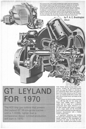
THIS WEEK British Leyland Motor Corporation unveiled the gas-turbine-erigined truck (see page 80) which it is showing at the Commercial Motor Show that opens at Earls Court today. Known as the GT truck, it is a six-wheeled double-drive tractive unit with a Rover-styled luxury cab based on the Ergomatic.
The Leyland 28 /350/R turbine develops up to 400 bhp (BS AU 141 rating) and weighs under 1,0001b, which is approximately half the weight of a comparable quality-built diesel engine. Because it is a two-shaft machine, peak torque is available at zero output speed and the favourable torque/speed relationship provides peak performance characteristics with a limited number of gear ratios.
A regenerator comprising two rotating low-speed heat exchangers provides a substantial reduction in fuel consumption by pre-heating the intake air from the compressor and variable power-turbine nozzles augment fuel economy in addition to affording overrun engine braking. Life expectancy is in the region of 12,000 running hours, which is equivalent to 300,000/500,000 vehicle miles. Servicing is facilitated by the use of a small number of self-contained subassemblies.
Dr. Albert Fogg, British Leyland's director of engineering, states that the unit is "the first prototype of a model that will go into limited production late in 1970". Adds Dr. Fogg: "It is not an engineering experiment or a purely prestige exercise."
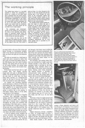
Mr. Noel Penny, general manager of Leyland Gas Turbines, has been largely responsible for the development of the turbine which is based on the Rover unit. The 38-ton-gross six-wheeled tractive unit to which the prototype gas turbine is fitted is described as eminently suitable for longdistance trans-continental operation at speeds around 70 mph. Because of the inherent flexibility of the gas turbine it is also suitable for stop-start urban running.
Leyland technicians point out that the turbine offers a substantial noise reduction in addition to a cleaner exhaust gas. Lowfrequency vibration is eliminated, which is of benefit to the driver and is conducive to longer chassis-component life. By removing heat from the exhaust gas the regenerator eliminates the nuisance of a "hot blast" from the exhaust stacks which are located vertically behind the cab.
The "gasifier" section—compressor and turbine—has a maximum speed of 38,000 rpm, while the power turbine operates at a maximum speed of 30,000 rpm. This is reduced by a single-stage helical gear to an output speed of less than 3,000 rpm. Easy starting from cold is facilitated by a hightension ignition system.
While the unit is normally operated on diesel oil, paraffin or a low-lead-content petrol, it can also be run on a variety of alternative fuels. These include any standard type of distillate fuel, liquid petroleum gas and gaseous fuels.
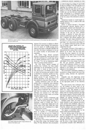
The rating of the turbine quoted earlier is the heavy-duty rating, the standard rating being 370 bhp. Minimum fuel consumption is 0.392 lb /bhp /h at 68deg F and 0.399 lb /bhp /h at 80deg F. The unit operates on a relatively low pressure ratio of 4 to 1 (at 80deg F) while the mass flow at this temperature is 3.75 lb /sec. Gasifier idling speed is 19,000 rpm and the full-load output-speed range corresponds to a maximum powerturbine speed of 0/3,250 rpm. The capacity of the wet sump of the lubrication system is 2gal.
Dimensions include an overall length excluding starter of 51in., a width of 28in. and a height of 44.2in.
Power is relayed through a five-speed fully-automatic epicyclic gearbox that is hydraulically operated and electrically controlled. There are two forward-drive positions of the control lever which is mounted centrally in the cab, the "low" position providing a selection of ratios that gives optimum performance and the "high" position a selection that affords optimum fuel economy. The ratio range comprises ratios of 5.22 to 1, 3.23 to 1, 2.125 to 1, 1.5 to 1 and (top) 1 to 1, the reverse ratio being 3.7 to 1. A gearbox full-torque power take-off runs at engine output speed and is controlled from the cab,
The primary structure of the engine is a close-grained iron casing which in plan view follows an H form, with the long sides forming the inner supports for the heatexchanger discs which are set longitudinally (rotating in the same plane as the road wheels).
The compressor turbine is integrally cast with blades of low-stress design to give long life. The gas generator assembly (compressor and compressor turbine on a common shaft) is supported on a roller bearing adjacent to the turbine and a ball bearing adjacent to the compressor.
The reverse-flow combustion chamber is mounted on a flange raised in the top of the pressure casing, between the regenerator discs.
Integrally cast, the single-stage power turbine is carried in a ball bearing at the turbine end and roller bearings at either side of the high-speed pinion in the reduction box.
The glass-ceramic heat exchanger discs are the product of many years of development in conjunction with the Corning Glass Co., USA. This material is chosen because it combines high-temperature capabilities with low thermal expansion and high heat-storage capacity. Pressure-loaded seals have been evolved to give low wear and low leakage, yet without absorbing a lot of driving power. The discs are self-cleaning.
Standard paper filters are fitted in the intake chamber to give adequate protection under normal road conditions; with six of them the replacement period is 1,000 hours. Twin 8in. exhaust ducts are swelled locally to 13in. diameter to incorporate silencers.
The engine is controlled solely by the starter switch and the throttle pedal.
The two driving axles of the bogie and the rear suspension of the UT truck are similar to the Bison units. Of the spiral-bevel type, the leading axle is operated by the through drive from a pair of helical gears and the drive is then relayed through an air-controlled lockable third differential to an output shaft on the rear of the casing and thence through an intermediate propeller shaft to the rearmost spiral-bevel axle. Both axles are fitted with epicyclic hub-reduction gears.
The axles are mounted on a rigid bogie in which each axle is located by radius rods and a pair of inverted semi-elliptic springs of the fully-floating type with centre trunnion bearings. The spring ends are free and rest on the spring brackets, the springs being secured at their centre to the trunnion bearing housing.
Of the beam type the front axle is a rigid I-section alloy steel forging carrying forged steel stub axles in phosphor-bronze bushes. The parallel king pins are located in the axle beam by cotter pins, the thrust being taken centrally on a hardened-steel button at the base of the pin. The wheel hubs are mounted on taper-roller bearings.
An integral unit providing hydraulic power assistance is a feature of the Burman recirculating ball type steering gear, power being supplied by an engine-driven pump. The unit has a constant ratio of 25.2 to 1 giving a positive feel to the steering. A twin-spoke steering wheel is of the safety type and has a 21in. diameter.
The front axle is mounted on Taperlite two-spring ultra lightweight semi-elliptic springs, each leaf of which is parabolically tapered along its length. This feature ensures that a constant stress is maintained throughout the spring and combined with pre-stressing of the leaves gives a substantially increased life, a weight saving of over 50 per cent and a much improved ride. The front of each spring is located by a no-maintenance rubber-bonded shackle pin and the rear with an all-rubber contrasonic shackle.
A full air braking system combines the service, secondary and parking-brake systems, air pressure being provided by an engine-driven compressor. The footbrake operates on all axles and controls the sys tem through a dual brake valve to which the brake pedal is connected mechanically. One half of the valve operates the tractor brakes utilizing direct acting brake chambers fitted adjacent to each wheel. The other half of the valve controls the trailer brakes via the service coupling line.
The secondary and parking brake functions are controlled by a single L-gate lever situated centrally in the driver's cab. The secondary brake is provided by the triplediaphragm brake chambers fitted to the front wheels of the tractor and by the trailer brakes, braking action being progressive. The parking function is provided by spring-actuated brake chambers on the tractor rear wheels, the springs being concentric with the service brake diaphragm.
The air system is based on two main reservoirs and an auxiliary reservoir and is fitted with an automatic water ejection valve actuated by the compressor unloader valve. A low-air-pressure warning buzzer is provided to draw the driver's attention to a malfunction of the air-pressure system.
A brake-drum diameter, lining width and
lining thickness of 6in. and lin. respectively are common to all axles, while total braking areas are 975 cu.in. for the foot brake and 650 cu.in. for the hand brake.
The frame is built of straight pressed-steel channel sections of 3in. by 9+m. by +in. that are fully braced with cross-members and strengthened over the section of maximum stress by a 4in. L-type flitch plate. Detachable one-piece steel-disc vented wheels are fitted with 11 22.5 tubeless tyres. The circular rolled-steel tank has a capacity of 75gal.
Vehicle dimensions include a wheelbase of I32in., an overall length of 241in., a track width of 74.25in., and a laden frame height of 38.581n. The length from the back of the cab to the rear of the frame is 176in.
Other details include a 24V electrical
system, a Butec alternator and starter and two 85 amp /h 12V batteries. Twin windtone electric horns, high output rectangular headlamps and double filament prefocus bulbs, combined sidelamps and flashers, combined stop-tail lamps and reflectors and electric windscreen wipers are includes in the equipment. All the instruments are grouped in a binnacle mounted directly in front of the driver and include a tachograph.