


HINTS ON MAINTENANCE.
Page 50
Page 51
If you've noticed an error in this article please click here to report it so we can fix it.
How to Get the Best Out of a Vehicle, to Secure Reliability and to Avoid Trouble.
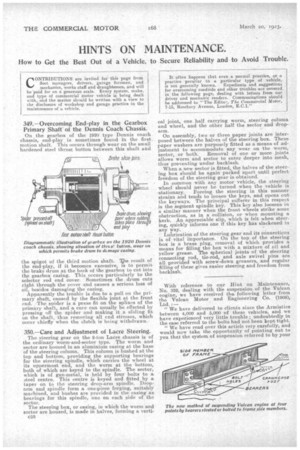
349.—Overcoming End-play in the Gearbox Primary Shaft' of the Dennis Coach Chassis.
On the gearbox of the 192(1 type Dennis coach chassis, end-play is sometimes found in the first, motion shaft. This occurs through wear on the small hardened steel thrust button between this shaft and
the spig o t of the third motion shaft. he result of
the end-play, if it becomes excessive, is to permit the brake drum at the back of the gearbox to cut into the gearbox casing. This occurs particularly to the selector rod end cover. Sometimes the drum cuts right through the cover and causes a serious loss of oil, besides damaging the casing.
• Apparently the trouble is due to a pull on the primary shaft, caused by the flexible joint at the front end.: The spider is a press fit on the aplines of the primary shaft, and a, cure can usually be effected by pressing off the spider and making it a sliding fit on the shaft, thus removing all end stresses, which occur chiefly when the clutch is being withdrawn.
350.—Care and Adjustment of Lacre Steering.
The steering gear on the 2-ton Lacre chassis is of the ordinary worm-and-sector type. The worm and sector are housed in an aluminium casing at the base of the steering column. This column is bushed at the top and bottom, providing the supporting bearings for the steering spindle, which carries the wheel at its uppermost end, and the worm at the bottom, both of which are keyed to the spindle. The sector, which is of gun-metal, is held by four bolts to a steel centre. This centre is keyed and fitted by a taper on to the steering drop-arm spindle. Droparm and spindle form a one-piece forging, suitably machined, and bushes are provided in the casing as bearings for this spindle, one on each side of the sector.
The steering box, or casing, in which the worm and sector are housed, is made in halves, forming a vertic53 cal joint, one half carrying worm, steering column and wheel, and the other half the sector and droparm.
On assembly, two or three paper joints are interposed between the halves of the steering box. These paper washers are purposely fitted as a means of .adjustment to accommodate any wear on the worm, sector, or both. Removal of one or more joints allows worm and sector to enter deeper into mesh, thus preventing undue backlash.
When a new sector is fitted, the halves of the steering box should be again packed apart until perfect freedom of the steering gear is obtained.
In common with any motor vehicle, the steering wheel should never be turned when the vehicle is • stationary. Forcing the steering in this manner strains and tends to loosen the keys, and opens out the keyways. The principal sufferer in this respect is the segment spindle key. This key also loosens in a similar manner when the front wheels strike some obstruction, as in a collision, or when mounting a kerb. An appreciable slip, which is felt when steering, quickly informs one if this key has slackened in any way.
Lubricatien a the steering gear and its connections is of vital importance. On the top of the steering box is a brass plug, removal of which provides a means for filling the box with a mixture of oil and yellow grease. The spherical joints of the steering connecting rod, tie-rod, and axle swivel pins are all provided with screw-down greasers and regular filling of these gives easier steering anefreedom from backlash.
With reference to our flint on Maintenance, No. 332, dealing with the suspension of the Vulcan engine, we have received the following letter from the Vulcan Motor and Engineering Co. (1906),
" We have delivered to clients since the Armistice between 4,000 and 5,000 of these vehicles, and we have experienced very little trouble undoubtedly in the case referred to the bolts had not been kept tight.
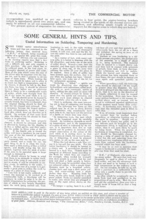
" We have read over this article very carefully, and would now take the opportunity of pointing out to you that the system of suspension referred to by your
correspondent was modified as per our sketch (which is reproduced) about two years ago, and can easily be altered on all our _commercial vehicles.
" Our present system of suspension for commercial vehicles is four point, the engine-bearing brackets being riveted to the inside of the channel section side members, and affording ample length of bearing support for the enginearms to which they are bolt-ed."