


ATEST MATADOR
Page 43
Page 42
Page 44
Page 47
If you've noticed an error in this article please click here to report it so we can fix it.
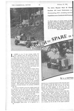
I0ADED to over 12 tons running weight, the A E.C. Matador Matk 111 chassis' had power to 4 spare when starting off on an incline of 1 in 41. The chassis, one of the first off the production line, had passed through its initial routine test before being handed over to me and had only 70 miles to its credit. Before the day was over, a further 90 miles or so were added, the route planned being of a severity sufficient to locate any probable fault. No faults could be found, and only minor adjustments to the clutch stop and brakes were made to obtain optimum performance.
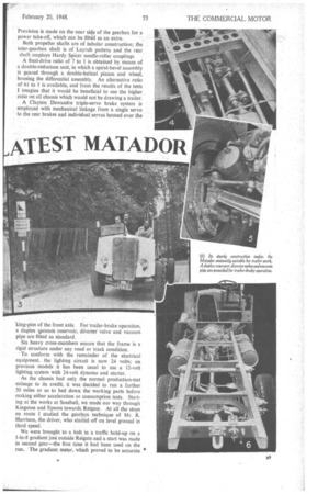
The power unit is the six-cylindered 9.6-litre directinjection oil engine, which; with a bore of 120 mm. and a stroke of 142 mm., develops 125 b.h.p. at a governed speed of 1,800 r.p.m. Dynamo, exhauster and fuelinjection pump are housed on the near side of the engine, a fuel-lift pump being driven 'off' the camshaft of the injection oil engine, which, with a bore of 120 mm. and with the Clayton Dewandre exhauster and, like the camshaft, is gear-driven from the crankshaft A twin V-belt on a pulley from the front of the crankshaft drives the dynamo and six-bladed-fan and water-pump assembly Built integrally witk the fuel-injection-pump coupling a flywheel dampens the pumping oscillations of the unit The valves are housed in the twin cylinder heads and are operated by long push-rods and flat-faced tappet blocks which ride on the camshaft. Thick steel-shell . bearings are used on main and big-end bearings, with a lining of white metal on the main-bearing upper halves and lead-bronze for the remainder of the shells.
Mounted as a unit with the engine and clutch, the four-speed gearbox is of constant-mesh pattern, with fourth and third speeds engaged by means of dog clutches Driven by a short shaft, the auxiliary gearbox provides a reduction of 1.58 to 1 as an alternative to the dog-engaged direct drive. It is operated by a 138 separate lever mounted just ahead of the main gear lever and arranged so that the direct drive in the auxiliary box can be engaged only after top gear in the main gearbox has been engaged. In the same way, an indirect gear in the main gearbox can be engaged only when the auxiliary lever is in the low position.
Thus, the combination of the four-speed main gearbox and the two-speed auxiliary box provides five forward speeds. This arrangement ensures that the highest indirect drive, which is normally used extensively on these heavy vehicles, is provided by the exceptionally wide gears of the auxiliary gearbox, which have a longer life than those of the main gearbox, where space limits face width. Both gearbox selector levers are mounted on a bracket on the off side of the engine crankcase. Provision is made on the near side of the gearbox for a power take-off, whichcan be fitted as an extra.
Both propeller shafts are of tubular construction; the inter-gearbox shaft is of Layrub pattern and the rear_ shaft employs Hardy Spicer needle-roller couplings. A final-drive ratio of 7 to 1 is obtained by means of a double-reduction unit, in which a spiral-bevel assembly is geared through a double-helical pinion and wheel, housing the differential assembly. An alternative ratio of 6i to 1 is available, and from the results of the tests
imagine that it would be beneficial to use the higher ratio on all chassis which would not be drawing a trailer.
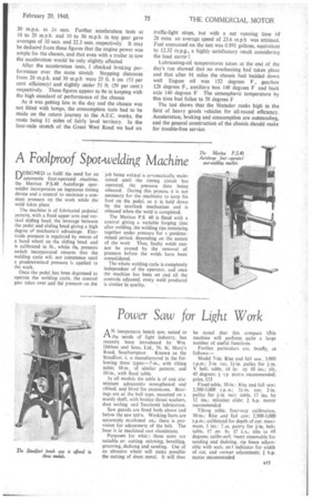
A Clayton Dewandre triple-servo brake• system is employed with mechanical linkage from a single servo to the rear brakes and individual servos housed over the . of the front axle. For trailer-brake operation, a duplex vacuum reservoir, diVerter valve and vacuum pipe are fitted as standard, •• Six heavy cross-members ensure that the frame is a rigid structure under any road or track condition.
To conform with the remainder of the electrical equipment, the lighting circuit is now 24 volts; on previous models it has been usual to use a 12-volt lighting system with 24-volt dynamo and starter.
-As the chassis had only the normal production-test mileage to its credit, it was decided to run a further 50 miles or so to bed down the working parts before making either acceleration or consumption tests. Starting at the works at Southall, we made our way through Kingston and Epsom towards Reigate. At all the stops en route I Studied the gearbox technique of Mr. R. Harrison, the driver, who started off on level ground in third speed. • We were brought to a halt in a traffic hold-up on a 1-in-8 gradient just outside Reigate and a start was made in second gear—the first time ithad been used on the . run: The'gradient.meter, which proved to be accurate on known gradients, gave some interesting gradient-gear data throughout the day's tests. Hills of 1 in 8 were climbed in third gear and 1-in-11 gradients were taken in fourth gear without unduly taxing the power unit. With so much power in hand I began to wish that we had a trailer in tow to put more load on the engine.
By this time we had worked our way around Godstone to Westerham, where I changed places with the driver. Westerham Hill presented no difficulty to the Matador, so we pressed on to Warlingham Green in search of Succombs Hill, listed in the R.A.C. handbook as 690 yds. of I-in-5i average gradient.
Approaching Succornbs Hill from Warlingham Green gave an opportunity of studying the gradient, as we made the descent first. After turning at the foot of the hill the radiator temperature was taken, the reading being 144 degrees F. and atmospheric temperature 63 degrees F.
I felt that the works driver would be more fitted to tackle the hill-climb, so we again changed places. Using second gear to begin the climb, a rapid change was made to third gear. On reaching the 1-in-4i stretch, a quick change back to second was made, and this ratio was held comfortably for the remainder of the hilt.
To see how the chassis would behave on the steepest gradient, we returned to a point where the meter read 1 ii 41 and started from this point. The works driver, knowing the chassis, selected second gear and started without abusing either clutch or engine. This perform
ance suggests that a very well-loaded trailer would be needed to enforce the use of first gear, even on a gradient of this order.
With no steeper hills in the area, we made our way across South-West London to Brentford weighbridge. I drove for this part of the journey and found the steering to be sufficiently light to enable me to weave my way through the slower traffic in the more congested thoroughfares. The brakes provided instantaneous response on the lightest pressure and ample power was available for emergencies. Gear changing was simple and I accomplished the run without crashing a gear.
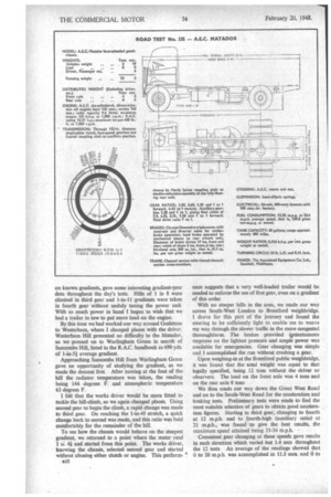
Upon weighing-in at the Brentford public weighbridge, it was found that the total weight was equal to that legally specified, being 12 tons without the driver or observers. The load on the front axle was 4 tons and on the rear axle 8 tons
We then made our way down the Great West Road and on to the South-West Road for the acceleration and braking tests. Preliminary tests were made to find the most suitable selection of gears to obtain good acceleration figures. Starting in third gear, changing to fourth at 12 m.p.h. and to fourth-high (auxiliary ratio) at 21 m.p.h., was found to give the best results, the maximum speed attained being 33-34 m.p.h.
Consistent gear changing at these speeds gave results in each direction which varied but 1.4 secs throughout the 12 tests An average of the readings showed that 0 to 20 mph. was accomplished in 11.3 secs. and 0 to
30 m.p.n. in 24 secs. Further acceleration tests at 10 to 20 m.p.h. and 10 to 30 m.p.h. in top gear gave averages of 10 secs. and 22,3 secs. respectively. It may be deduced from these figures that the engine power was ample for the chassis, and that even with a trailer in tow the acceleration would be only slightly affected After the acceleration tests, I checked braking performance over the same stretch Stopping distances from 20 m.p.h. and 30 mph • were 25 ft. 6 ins (53 per cent. efficiency) and slightly under 5t ft (59 per cent.) respectively. These figures appear to be in keeping with the high standard of performance of the chassis As it was getting late in the day and the chassis was not fitted with lamps, the consumption tests had to be made on the return journey to the A.E.C. works, the route being 11 miles of fairly level territory. In the four-mile stretch of the Great West Road we had six traffic-light stops, but with a net running time bf 28 mins an average speed of 23.6 in.p.h was attained. Fuel consumed on the test was 0 891 gallons, equivalent to 12.32 m.p.g., a highly satisfactory result considering the load carriel.
Lubricating-oil temperatures taken at the end of the day's run showed that no overheating had taken place and that after 91 miles the chassis had bedded down well Engine oil was 152 degrees F, gearbox 128 degrees F., auxiliary box 148 degrees F and back axle 140 degrees F The atmospheric temperature by this time had fallen to 58 degrees F
The test shows that the Matador ranks high in the field of heavy goods vehicles for all-round efficiency. Acceleration, braking and consumption are outstanding, and the general construction of the chassis should make for trouble-free service.