


Useful Charts and Tables. No. 2.
Page 4
If you've noticed an error in this article please click here to report it so we can fix it.
By George Watson, A.M.I.Mech.E.
Helical Springs or Motor Vehicles.
Helical compression, or tension, springs are used for so many purposes on motor vehicles, and the formula for their design is so intricate, involving, as it does, the third and fourth powers of extremely small quantities, that the designer is often tempted to guess at the size of wire and the number of coils, or is guided by some spring previously used for a similar purpose. Many more or less abreviated formulx have been devised, but the results obtained by their use are not always reliable.
Mr. Wilson Hartnell has made some careful experiments on helical springs while engaged in perfecting the expansion governor, and he gave the results of his experiments in a paper read before the Institution of Mechanical Engineers. Mr. Wilson Hartnell's figures show that, as the diameter of the wire decreases, the percentage of" hard skin " increases ; consequently, the maximum stress may be increased in proportion. Thus, for a inch diameter wire, the stress was to,noolb. per square inch, and for a * inch diameter wire the stress was 12,000lb. per square inch. Taking Mr. Hartttell's figures as being the best which have come under the writer's notice, and which can always be relied upon to give :accurate results in practice, the accompanying charts have teen prepared.
From chart No. r, the maximum safe load for any given ;gauge of wire, and mean diameter of coil, can be read off at at glance, or, lithe load to be put upon the spring is a known 'factor, then the gauge and mean diameter of coil may sinailarly be obtained. Having decided the gauge and mean diameter from chart No. 1, the designer should now refer to chart No. 2, from which the " rate " or load which would -cause a deflection of one inch on the spring may he obtained. The deflection may be either by extending or compressing the coils. The number of coils for a given " rate " may also be obtained from this chart.
The scales are all logarithmic, and give a reading equal in accuracy to the slide rule, with this important difference, the position of the decimal place is never in doubt.
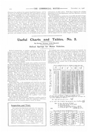
In isolated cases where extreme accuracy is required, the following table of constants has been prepared, and from it the values of KD3 and CD4 may be read off at a glance for all gauges from 4/0 to 20 S.W.G., which covers all the sizes in general use on motor vehicles. The supplementary table gives the value of R3 for sizes between x-16 inch and z inches mean radius. Although these charts are prepared especially for wire of round section, they may equally be applied for square section wire if the reading from them is multiplied by 0.36.