


A NOVEL Multi-speed Easy-change GEARBOX
Page 51
Page 52
If you've noticed an error in this article please click here to report it so we can fix it.
WIRE main two shortcomings of the 1. orthodox gearbox, as used on the majority of motor vehicles, are, first, the difficulty of changing gear at high speeds, and, secondly, the fact that unless some auxiliary two-speed device be employed, only three or 'four speed ratios are available. Consequently, there should be a wide scope for a gearbox of the type described in this . article, in which five or seven forward-speed ratios . can . readily be provided, together . with a gear change requiring no skill. Furthermore, a change from one'forwfird speed ratio to another does not involvegoing through neutral and the load is not "-dropped "; consequently, there is no risk of missing a gear when proceeding uphilL
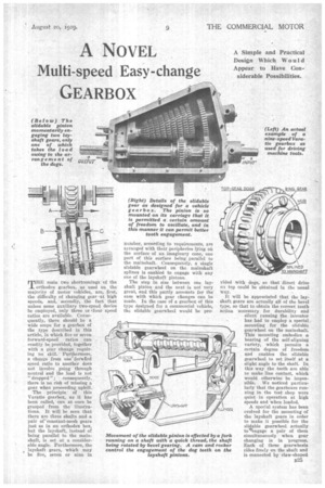
The principle Of this Varatio gearbox, as it has been called, can at once be grasped from the illustrations. It will be seen that there are three shafts and -a pair of' constant-mesh gears just as in an orthodox box, but the layshaft, instead of being parallel to the mainshaft, is set at a considerable angle. Furthermore, the layshaft gears, which may be five, seven or nine in
number, according to requirements, are arranged with their peripheries lying on the surface of an imaginary cone, one part of this surface being parallel to the mainshaft. Consequently, a single slidable gearwheel on the mainshaft splines is enabled to engage with any one of the layshaft pistons.
The step in size between one layshaft pinion and the next is not very great, and this partly accounts for the ease with which gear changes can be made. In the ease of a gearbox of this type designed for a commercial vehicle, the slidable gearwheel would be pro
vided with dogs, so that direct drive oil top could be obtained in the usual Way.
It will be appreciated that the layshaft gears are actually all of the bevel type, so that to obtain the correct tooth action necessary for durability and silent running the inventor has had to employ a special . mounting for the slidable gearwheel on. the mainshaft. This mounting embodies a hearing of the self-aligning variety, which permits a certain degree of freedom and enables the slidable gearwheel to set itself at a slight angle to the shaft. In this way the teeth are able to make line contact, which would otherwise be impossible. We noticed particularly that the gearboxes running in the test shop were quiet in operation at high speeds and when loaded.
A special system has been evolved for the mounting of the layshaft gears in order to make it possible for the sli4able gearwheel actually to.7eitgage a pair of them simultaneously • when gear changing is in progress. Each of these gearwheels rides freely on the shaft and is connected by claw-shaped
dOgs to its fellow at each side. In this *ay the whole cluster of gearwheels is coupled one to another, and. the dogs are all held'qn engagement by means of a coil spring placed at one end.
In thegearboxes so far built' for industrial purposes, such as driving textile machinery, the selector fork is traversed by a screw thread operated by bevel gears and a hand wheel. At one end of the threaded shaft there is a cam operating a plunger which passes down the centre of t4e layshaft and forces one of the gearwheels back against the spring pressure. What actually happens when the slidable gearwheel commences to move is that the cam and push rod compress the spring and allow a certain freedom of motion to the layshaft gearwheels. Consermently, at the moment when two of these are engaged, -such as those marked B and C in the separate drawing reproduced, one is transmitting load, whilst the other is free. When the slidable gearwheel A leaves the pinion B and runs into mesh with the gearwheel C, the cam frees the spring and all the dogs are once again engaged.
An arrangement is also made whereby the push rod is operated When the slidable gearwheel is moved rearward from the bottom-gear position and Wore it actually !funs into mesh with the smallest of the layshaft gearwheels. A neutral position is thereby obtained owing to the freeing of the dogs,
although the gears are actitally still in mesh. For reverse gear it would, only be necessary to provide another pair of pinions with wlAch --the slidable gearwheel could engage if moved rearwards from this neutral position:
Although this interesting gearbox has not yet been tried in a chassis on the road, it has been put through some very strenuous tests extending over a period of two years, and has, we are' told,
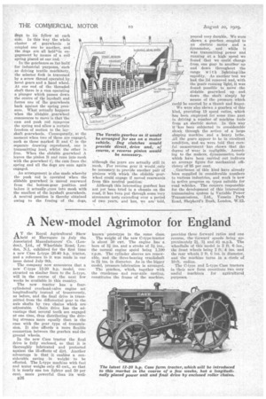
proved very durable. We were shown a gearbox coupled to an electric Motor and a dynamotor, and while it was transmitting power and running at a high. speed we 'found that we could Change from one gear to another up and down throughout the range with lightning-like rapidity. As 'another test we had the lid removed and, with the-gears running light, it was found possible to move /the slidable gearwheel up and down the shaft simply by means of the • pressure which . could be exerted by a thumb and finger.
We were also shown a gearbox of this kind, providing 19 speed ratios, which has been employed for some time past in driving a number of machine tools from an electric motor. In this way it has been subjected to considerable shock through the action of a large shaping machine and a heavy lathe. All the gears appear to be in excellent condition, and we were told that careful measurement has shown that the degree of wear is negligible. According to the makers, dynamometer, tests which have been carried out indicate an average figure for mechanical efficiency of 95 per cent.
Gearboxes of this kind have already been supplied in considerable numbers to various industries, and work is now in active progress on types suitable for road vehicles. The concern responsible for the development of this interesting transmission system is Variable • Power Transmissions, Ltd. Vassein Park Road, Shepherd's Bush, London, W.12.