


Patents Completed.
Page 38
If you've noticed an error in this article please click here to report it so we can fix it.
New Crossley Sleeve-poppet Valve. Adjustable Roller Bearings. cooled Sleeve Valves. Checking Lear-spring Vibration.
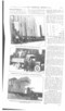
Water CROSSLEy Morons, Tiro., and A. W. REsivus, No. 29,704, dated 24th December, 1913.—The object of this invention is to provide valves so arranged that:—A high volumetric efficiency is obtained at high speeds; the working is more silent; the exhaust valve is balanced ; the surface area of the combustion chamber is small; both inlet and exhaust valves are readily accessible.
The working cylinder is provided with two sets of annular ports in the combustion chamber. The lower ones constitute the inlet, and they are controlled by a sleeve valve moving axially in the cylinder. A conical seating is provided, and the valve is bedded down on to this.
The upper ports are for the exhaust, and they are controlled by a second sleeve which lies outside the first sleeve. A similar conical seating is provided for these, and a series of ports in the inlet valve permit the exhaust to pass outward when the outer valve is lifted. Owing to the very large effective area of the valves, the lift can be considerably reduced, and the inertia forces of the valves and valve mechanism are reduced to a minimum.
4.. HART and K. J. AtstFELT, No. 22,147, dated 1st October, 1513.—The roller bearing described in this specification is specially arranged for adjustment to compensate for wear. The rollers, which are tapered, are arranged in two or more circular rows and held in place by a cage. They run between tracks which lie at an angle to one another. In the construction illustrated there is one inner track for the two rows of rollers, and two outer tracks, one for each row of rollers. These outer tracks are held in place by a sleeve, and they can be adjusted by a ring which screws into the sleeve. This ring is locked in place by a spring wire.
When it is desired to adjust the bearings the locking wire is removed and the ring screwed up in the sleeve to the required extent. The locking wire is then replaced. The specification describes several modified ways of adjusting the rollers.
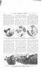
T. J. FAY, No. 15,834, dated 9th July, 1913.—This specification describes an internal-combustion engine having a watercooled sleeve valve. A cylindrical chamber at the side of the cylinder has a fixed hollow abutment in it to close the interior of the valve.
The abutment is reduced in diameter at its upper end, opposite the cylinder port, and ports in the sleeve valve can be brought to register with the cylinder port so that corn munication is established between the cylinder and the upper annular portion of the valve chamber. A stand-pipe projects into the interior of the hollow abutment and delivers cold water to it, the water passing out into the cylinder jacket. In the construction illustrated the cooling water is introduced from the upper end of the valve chamber, and thermo
syphon circulation is relied upon. In an alternative construction, also described and illustrated in this specification, the cooling water is supplied through the lower end of the abutment, and a pump may be used to give positive circulation.
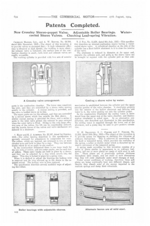
W. H. BRADBTJRN, S. C. FORDER and P. FORDER, No. 11,319, dated 15th May, 1913.—The object of this invention is to provide means for damping or checking the vibration of ordinary leaf-springs. This is achieved by associating with the hard or tempered metal, which provides the resiliency of the spring, a softer or ductile metal which is distorted by excessive movement of the tempered spring. A spring made according to this invention consists of a aeries of plates similar in appearance to an ordinary leaf. spring, but one or more plates are made ef mild steel or soft iron. These plates are of practically uniform thickness throughout their length, and are made of such dimensions that they will yield elastically under small changes of load. Under severe conditions of working, therefore, these soft plates are being continually bent into different shapes, and thereby they absorb some of the energy imparted to the resilient springs and damp their vibrations.