


Heat Regenerator in Piston Engme
Page 50
If you've noticed an error in this article please click here to report it so we can fix it.
THE useful work in a charge of hot gases is only partly used in the normal type of engine, some being
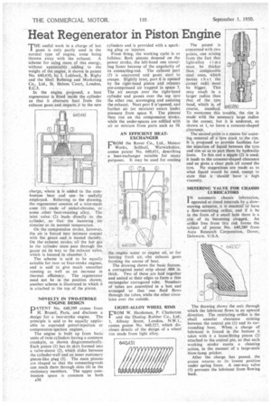
thrown away with the exhaust. A Scheme for using more of this energy, without appreciablY adding to the weight of the engine, is shown in patent No, 640,410, by 1. Lubbock, R. Rigby and the Shell Refining and Marketing Co., Ltd., St. Helens Court, London, E.C.3. • In the engine proposed, a heat regenerator is fitted inside the cylinder so that it abstracts heat from the exhaust gases-and iMparts it to the new
charge; where it is added to the combustion heat and can • be usefully employed. Referring to the drawing, the regenerator. consists of a •wire-mesh cane.: 1):. made • of nickel-chrome, or. some .other heat-resisting alloy. The inlet . valve-: (2) leadsdirectly to the cylinder, . so that the incoming,. air remains' 'at its normal temperature. , On the:comPressiOn stroke, however, the air is forced into intimate contact with the, gauze and is heated thereby. On the. extia'utst stroke, 'all the hotgas in the cylinder must pass through the gauze on its way to the exhaust valve, which is located in chamber 3.
The scheme is said to be equally suitable for two-.or four-stroke engines, and is said to give much. smoother running as well as .an increase in thermal efficiency. The regenerator need not be in. the position shown; another scheme is illustrated in which it is attached to the top of the piston.
NOVELTY IN TWO-STROKE ENGINE DESIGN
PATENT No. 640,399 comes from H.' Brunel, Paris, and discloses a design for a two-stroke engine. The principle is said to be equally applicable to aspirated petrol-injection or compression-ignition engines.
The engine is built up from basic units of twin cylinders having a common crankpin, as shown diagrammatically. Each piston (1) has its skirt formed into a valve-sleeve (2), which slides between the cylinder-wall and an inner stationary piston-like plug (3). The main pistons are shaped so that the connectinvrods can reach them through slots (4) in the stationary members. The upper combustion space is common to both cylinders and is provided with a sparking plug or injector.
From firing, the working cycle is as follows: Both pistons descend on the power stroke, the left-hand one travelling faster because of the angularity of its connecting-rod. The exhaust port (5) is uncovered and gases start to escape. Slightly later, port 6 is opened by the right-hand piston and releases pre-compressed air trapped in space 7. The air sweeps over the right-hand cylinder and passes over the top into the other one, scavenging and assisting the exhaust. Next port 8 is opened, and further air (or mixture) enters Under pressure . from space 9. The pistons then rise on the compression stroke, while the under-spaces are refilled with air or mixture from ports such as 10.
AN EFFICIENT HEATEXCHANGER
EiROM the Rover Co., Ltd., Meteor Works, Solihull, Warwickshire, comes patent No. 640,431, describing a heat-exchanger suitable for many purposes. It may be used for cooling the engine water or engine oil, or for heating fresh air, -the eihaust gases forming the source of heat.
The drawing shows the basic feature, a corrugated metal strip about :004 in. thick. Two of these are laid together and united at their edges to form a thin rectangular corrugated tube. Numbers of tubes are assembled in a box and arranged so that one fluid flows through the tubes, while the other circulates over the outside.
LIGHT-ALLOY WHEEL RIMS
FROM W. Hardeman, P. Chatterton and the Dunlop Rubber Co., Ltd., 1, Albany Street, London, N.W.1., comes patent No. 640,327, which discloses details of the design of a wheel rim made from light alloy. The patent is concerned with two points, one arising from the fact that light-alloy rims must be thicker than comparable steel ones, which means that -the corner radii • must be bigger. This may result in a larger radius than that of the tyre bead, which is, of course, standard. To overcome this trouble, the rim is made with the necessary large radius in the corner, but it is undercut, as shown at 1, to leave a crescent-shaped clearance.
The second point is a means for-assisting removal of a tyre stuck to therim. It is proposed to provide facilities for the injection of liquid between the tyre and rim so as to part them by hydraulic force. To this end a nipple (2) is used; it leads to the crescent-shaped clearance and so gives a clear limit all round the tyre. No suggestions are made as to what liquid would be used, except to state that it 'should have g high viscosity.
METERING VALVE FOR CHASSIS LUBRICATORS I N automatic chassis lubrication, operated at timed intervals by a slowmoving actuator, it is' essential to have a flow-restricting orifice, and if it be in the form of a small hole there is a risk of its becoming clogged. An orifice free from this risk forms the subject of patent No. 640,280 from Auto Research Corporation, Dover, Delaware. U.S.A.
The drawing shows the unit through which the lubricant flows in an upward direction. The restricting orifice is the sfnall annular clearance existing between the central pin (1) and its surrounding bore, When a charge of lubricant is forced in the bottom it takes with it a loose-fitting piston (2) attached to the central pin, so that each working stroke exerts a cleaning action, in the manner of a large-scale blow-lamp pricker.
After the charge has passed, the piston returns to its lowest position under spring force. A one-way valve (3) prevents the lubricant from flowing back.