


Tilling-Stevens Express
Page 48
Page 49
If you've noticed an error in this article please click here to report it so we can fix it.
Comes Back THE former Tilling-Stevens Express coach was noted in its time for straightforward design. good performance and passenger comfort. A 30-ft. successor to this popular model has now been introduced by Tilling-Stevens, Ltd., Maidstone, and is named the Express Mark II. It is a medium-weight, forward-control singledecker of simple design, which is to be produced at £400-£500 below the cost of the normal maximum-load under
floor-enained chassis, and the body is designed for only three or four fewer passengers than the flat-engined models.
The engine is relatively small when compared with those of high-powered maximum-capacity buses, and all other units are of a corresponding size, thus affording a reasonable power-to-weight ratio and economy. During consumption trials, 16-20 m.p.g. has been obtained, according to the route and conditions of the trials.
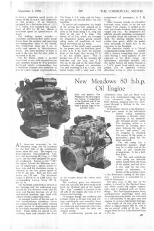
The power unit is the new Meadows 4 DC.330 oil engine, which has been on the secret list for some time. Details have been released to-day and the unit is more fully described on the next page. It is a four-cylindered 5.43-litre
A34 direct-injection oil engine, developing 80 b.h.p. at 2,200 r,p.m.
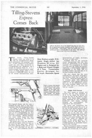
Extended tests of the 'prototype chassis incorporating this unithave shown its performance to be beyond reproach. It is mounted in the chassis as a unit with the clutch and gearbox, employing a rubber-bushed toggle-link arrangement at the front, and -two Silentbloc bushes, one each side of the flywheel housing, at the rear.
The new chassis has the latest Tilling-Stevens five-speed directsdrive-. tOp gearbox, which has a split lightalloy case. Third and fotIrth ratios are in constant mesh, with sliding-dog engagement. „First, second and reverse gears are of the sliding-spur pattern, the ratios available being 7.52, 4.27, 2.375, 1.473 and I to I forward, and 7.81 to I reverse.
Engine Well Forward The short engine is situated well forward and the long wheelbase of 18 ft. 7/ ins, places the driven axle towards the rear of the chassis, consequently three Hardy .Spicer propeller shafts supported by two self-aligning double-row ball steady bearings, mounted on cross-members, are employed in the transmission.
The power and transmission line follows the frame centre line as far as the rear"of the second propeller shaft, and from this point the final shaft is connected to the offset pinion of the hypoid gear in the rear axle. This axle has been designed and produced by Tilling-Stevens, Ltd., the case comprising a cast centre housing, with two axle tubes, which are spigoted and bolted to the centre portion. The hypoid pinion of the final drive is straddle-mounted on pre-loaded duplex tapered-roller bearings.
Because the Express coach is intended for fast long-distance operation and is available for overseas use, it is required to have a maximum speed greatly in excess of the 30 m.p.h. limit applicable to this country. It is, therefore. equipped for a final-drive ratio of 5.125 to 1, which, with standard tyre equipment of 8.25 by 20 ins., affords a. maximum speed of approximately 50 111.11.11.
The braking system includes a Lockheed continuous-flow servo pump driven from the gearbox and operating two-leading-shoe units at all wheels. The front-brake shoes are 3 ins. in width and operate in 16-in.-diameter. drums. The same diameter of druin is used at the rear, but the shoe width is increased to 41 ins.
The flat frame, which is parallel from front to rear, with channel-section side members braced by 4-in'.-diameter die-forged tubular cross-members, has a bolted-on dropped rear extension to prov:de ample luggage accommodation. The frame is 3 ft. wide, and the frontaxle springs are secured below the side members.'
To To obtain soft suspension, the length of the springs has been stepped up to the maximum for a single-decker, the units at the front being 4 ft. long and those . at the rear 5 ft. long. The leaves, all of 3-in, width, are arranged for progressive action, giving smooth riding , under all conditions of load. Shock absorbers are not fitted.
Because of the small, space occupied by the power unit the bulkhead panel is only 4 ft. 6 ins, from the extreme front of the body, 'thus leaving 25 ft. 6 ins, for saloon space. ' This is '• divided into .16 ft. 44 ins, between the, bulkhead and rear axle, and 2 ft. 104 ins, to the end of the main frame, excluding the dropped rear extension.: The rear ovethang as 9 ft. 14 ins. The frame height, with a body and a full
complement of passengers, is 2 ft. 81
Other features include an all-welded fuel-tank strap, which, as on the new Vulcan 7-ton chassis, is welded to the tank and chassis brackets, thus reducing weight and cost. An inexpensive but efficient draught-excluding arrangement is provided round the controls at floor level, the steering column having a rubber boot gaiter, whilst the pedals have surrounds of horse hair in the apertures in the footplate. ,• • • The electrical circuit is a 24-volt .
compensated-voltage-control system,' With a 'battery coniprising fotfr 6-volt Unitshiving: a total capacity of :154 amp.-hrs. at the 10-hr. rating. All instruments, road-light switches and ' the starter button are neatly housed in.
C.A.V. panel, from which any.coirponent can be removed withotut disturbing wiring or other instrumens.