


FODEN MOVES THE ENGEN TO THE REAR
Page 40
Page 41
Page 42
If you've noticed an error in this article please click here to report it so we can fix it.
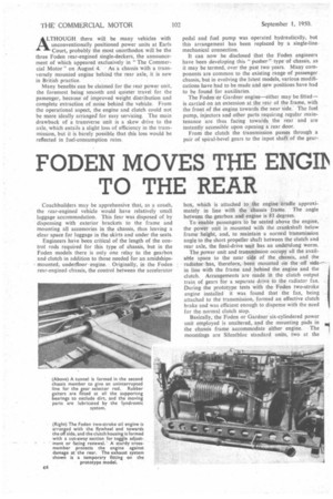
ALTHOUGH there will be many vehicles with unconventionally positioned power units at Earls Court, probably the most unorthodox will be the three Foden rear-engined single-deckers, the announcement of which appeared exclusively in "The Commercial Motor" on August 4. As a chassis with a transversely mounted engine behind :the rear axle, it is new in British practice.
Many benefits can be claimed for the rear power unit, the foremost being smooth and quieter travel for the passenger, because of improved weight distribution and complete extraction of noise behind the vehicle. From the operational aspect, the engine and clutch could not be more ideally arranged for easy servicing. The main drawback of a transverse unit is a skew drive to the axle, which entails a slight loss of efficiency in the transmission, but it is barely possible that this loss would be reflected in fuel-consumption rates.
Coachbuilders may be apprehensive that, as a coaeh, the rear-engined vehicle would have relatively small luggage accommodation. This fear was disposed of by dispensing with exterior brackets to the frame and mounting all accessories in the chassis, thus leaving a clear space for luggage in the skirts and under the seats.
Engineers have been critical of the length of the control rods required for this type of chassis, but in the Foden models there is only one relay to the gearbox and clutch in addition to those needed for an amidships, mounted, underfloor engine. Originally, in the Foden• rear-engined chassis, the control between the accelerator
pedal and fuel pump was operated hydraulically, but this arrangement has been replaced by a single-line mechanical connection.
It can now be disclosed that the Foden engineers have been developing this " pusher " type of chassis, as it may be termed, over the past two years. Many components are common to the existing range of passenger chassis, but in evolving the latest models, various modifications have had to be made and new positions have had to be found for auxiliaries.
The Foden or Gardner engine—either may be fitted— is carded on an extension at the rear of the frame, with the front of the engine towards the near side. The fuel pump, injectors and other parts requiring regular maintenance are thus facing towards the rear and are instantly accessible upon opening a rear door.
From the clutch the transmission passes through a pair of spiral-bevel gears to the input shaft of the gear box, which is attached to the engine cradle approximately in line with the chassis frame. The angle between the gearbox and engine is 83 degrees.
To enable passengers to be seated above the engine, the power unit is mounted with the crankshaft below frame height, and, to maintain a normal transmission angle to the short propeller shaft between the clutch and rear axle, the final-drive unit has an undetslung worm.
The power unit and transmission occupy all the avail able space to the near side of the chassis, and the : • radiator has, therefore, been mounted on the-off side-• in line with the frame and behind the engine and the clutch. Arrangements are made in the clutch output train of gears for a separate drive to the radiator fan. During the prototype tests with the Foden two-stroke engine installed it was found that the fan, being attached to the transmission, formed an effective clutch brake and was efficient enough to dispense with the need for the normal clutch stop.
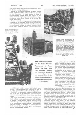
Basically, the Foden or Gardner six-cylindered power unit employed is unaltered, and the mounting pads in the chassis frame accommodate either engine. The mountings are Silentbloc standard units, two at the
front of the engine and a single horizonal bracket above the flywheel housing at the rear.
Because of the radiator position, the water cooling system has been modified and a new housing provided for the thermostat. A single silencer is fitted to Gardner-engined chassis, whilst the exhaust of the Foden two-stroke engine is passed through three stages of silencing before being expelled at the off-side rear corner of the chassis.
For the twd-stroke oil engine, an oil-cooling radiator is installed on the outer side of the normal cooling unit. The lubricating system has been altered so that oil leaving the pump is fed to the radiator through a distribution valve. From the radiator it is conducted to the normal filters, in which a pressure-relief valve is incorporated. The distribution valve, regulates the flow of oil and is operative between 80 and 180 degrees F.
• Fuel filters are attached to brackets from the timing case at the rear of the engine and are accessible for maintenance through bonnet doors at the rear of the chassis.
The Foden standard 151-in.-diameter single-dry-plate clutch is fitted, but a nem; housing has been developed to provide a large aperture towards the rear of the vehicle through which normal adjustments can be made or the complete unit can be removed. This housing, a light-alloy casting, is extended to accommodate the clutch output shaft and spiral gears are interposed between the clutch and gearbox.
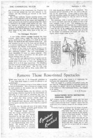
(Above) in the rearrangement of components the radiator has been put behind the engine and the bottom water pipe extended from the radiator across the frame to the pump. The two pipes rising vertically are the feed lines between the hydraulic reservoir pump and accumulator of the braking system. (Left) The radiator incorporates cooling tubes for the engine lubrication system, and the header tank of the water cooling system is extended for use with the Gardner power unit.
An additional train of helical gears is required for the fan drive, the fan spindle being higher than the clutch housing. These .gears are also retained in the clutch housing. A spring-loaded friction' unit is incorporated in the fan drive and the fan is a six-bladed, pressed-steel unit 21 ins, in diameter, which revolves in a full shroud.
The Foden four-speed gearbox or the five-speed close-ratio unit, with super-low gear for the low forward and reverse ratios, can be supplied. Apart from the low and super-low gears, all others are in constant mesh and are engaged by multisliding dogs.
A normal gear lever is fitted. The linkage between the lever and gearbox employs four tubular shafts with mechanically jointed couplings and is supported throughout the length of the frame by three long, split, white-metal-lined bushes. Rubber boots are fitted between the bearings and shafts to prevent dirt from reaching the bearing surfaces, and a Syndrornic automatic lubrication system ensures that all the moving parts are fully lubricated.
The clutch controls consist of a series of four rods connecting through relay levers to the operating mechanism at the rear of the chassis. A short mechanically jointed shaft, the joints of which are in the neutral position when under full load, connects the output flange of the gearbox to the underslung worm drive, which is offset towards the off side of the chassis. In
the arrangement of the components, the 32-gallon fuel tank is carried behind the rear axle adjacent to the radiator and the batteries are housed in the frame amidships.
The Foden hydraulic booster braking system, with Foden two-leading-shoe units at all wheels, is employed, the pump being driven by the engine and supplying oil under pressure to the reservoir and operating unit, which is attached to the engine cradle behind the axle. This has required a rod and lever linkage from the brake pedal to the operating unit at the rear. Both axles are equipped with 161-in.-diameter brake drums, the front shoes being 4i ins, wide, whilst those at the rear are 7 ins. wide.
No Outrigger Brackets A new frame, without outrigger brackets, has been evolved. Apart from a slight rise from the rear-axle spring dumb-iron to the engine, it is level on the top flanges, the depth of the side members being 9 ins. The side members are set in at the front and are braced by a cruciform member at the centre, as well as by boxed pressed-steel and tubular cross-members.
A feature of the frame is the spring bracket at the rear, which is incorporated in a deep cross-member to give additional support. The rear cross-member is made detachable to assist in engine removal. This member also forms a protection for the power unit against damage from the rear.
There are leftand right-hand-drive versions, and the overall width can be 7 ft. 6 ins. or 8 ft. All the current models have a 16-ft. 6-in. or 19-ft. 6-in, wheelbase for bodies 30 ft. or 33 ft. long respectively. The wheelbase provides even tyre loading and permits the same size of tyre to be used on all wheels. The 7-ft. 6-in, wide models are shod with 9.00 by 20-in. tyres, whilst the 8-ft. wide chassis have 10.00 by 20-in. equipment. The minimum ground clearance at the rear axle is 10i ins. and 111 ins. respectively. Frame height is lower than with the underfloor engine, the height of the frame with the body unladen being 2 ft. 10i ins. and 2 ft. 7i ins. with full load.
The prototype, with a mock-up platform and seats for driver arkd mate, and with 16 gallons of fuel in the tank, weighed 4 tons 11 cwt. The weighing was conducted at Sandbach and observed by a representative of "The Commercial Motor." 1 he distribution showed 3 tons 10 cwt. to be supported by the rear axle and 1 ton 1 cwt. by the front. This prototype was powered by the Foden six-cylindered two-stroke 126 b.h.p. oil engine, which weighs under 10 cwt.