


REDUCING THE WEIGHT THE POST-WAR VEHICLE
Page 26
Page 27
Page 28
If you've noticed an error in this article please click here to report it so we can fix it.
Effects of Weight Reduction on Performance are Discussed, and the Properties of Structural Members Composed of Four Different Lightweight Materia" ls are Compared With Those of Equivalent Members in Mild Steel
ATHOROUGH examination of the effects df ,weight .reduction in road-transport vehicles would entail the compilation of a large volume, It would be necessary to discuss the uses and advantages of light alloys in the engine, the effects on performance of weight reduction in the body, framework and chassis, and the economic significance of such effects. ,
From the operator's point of view, the most important advantages to be gained by weight reduction are undoubtedly the lowering of the taxation class of a given type of vehicle and/or the replacement of a considerable proportion of unnecessary dead weight by useful payload. In the present survey, therefore, we will consider briefly the extent ta which performance is influenced by the weight of the vehicle, and, in addition, compare the properties of some typical lightweight constActionar materials with those of mild steel.
• The total resistance opposing the motion of a Vehicle is constituted of two components—wind resistance and rolling resistance. The first of these is independent of the weight of the vehicle, being a function of its frellipid,
area and its speed relative to the atmosphere. The second is greatly influenced by the weight, being due to ' mechanical and frictional losses in' the vehicle itself and at the sin-faces of contact with the road.
Light Materials to Aid the Reduction of Rolling Resistance We are, of course, herein concerned primarily with the reduction of rolling resistance by the adoPtion of light materials. Nevertheless, in order that this factor may be viewed in correct perspective, it is desirable to give scene consideration to the relative importance of wind resistance.•
The total wind resistance inpounds an the front• of a vehicle may be. readily estimated from the simple expression: 0.002040 . . . . (1) where a denotes the area in sq. ft. and v the speed in m.p.h. Moreover, the horse-power required to overcome thatpressure amounts
• Total wind pressure x v to : . . . . (2).
375 •
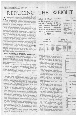
Adopting these expressions and assuming a frontal area of 35 sq. ft., the two curves in Fig. 1 have been plotted. An area of 35 sq. ft: has been chosen arbitrarily; in actual practice the area may be considerably greater, e.g., in the case-of a tanker, or less in the case of a small van. The value selected will, however, serve to give some indication of the magnitude of the wind resistance encountered in practical cases.
As we can see, at low speeds up to abcwit 20 m.p.h. Or 30 m.p.h., wind resistance is of no great importance,
• but at higher speeds it rises with great rapidity until, at speeds approaching the maximum of the vehicle; practically the whole of the available horse-power is expended in overcoming this resistance.In. the present instance, for example, we see that the required horse-power is about 16 at 40 m.p.h. anc1.53 at 60 m.p.h. The horse
power actually developed must be appreciably greater than that indicated by the curve, as expression (2) takes no account of rolling resistance or transmission losses.
In short, the major resistance 'encountered at high speeds cannot be offset by weight reduction, but losses due to the above cause can be minimized by careful design of body and chassis, coupled whenever practicable with streamlining.
Although rolling resistance increases with vehicle weight, at normal cruising speeds it is of considerably.
smaller moment than wind resistance. If it were possible tb operate vehicles minty at uniform speeds, and on straight, level roads, the influence of weight on a vehicle of given horsepower would be comparatively small. Howeyer, under practical running conditions, the necessity of frequent
acceleration and deceleration, hillclimbing and cornering, renders the
weight factor one of great importance. From elementary dynamics we know that the force required to impart
a given acceleration to a' body is proportional to the mass of that body;
whenever work is done against gra.vi tatiOnal action, as in hill-climbing, or when the direction of motion is
changed, as in cornering, the effort is again dependent ruPonthe Weight involved.
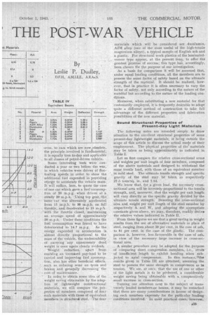
A particularly clear -illustration of the effect of weight on fuel consumP'lion was provided, some years ago, by Mr. A. Taub,-in a paper read before
the Society of_Automotive Engineers. (See S.A.E. Journal, June, 1930.) Mr. Taub determined the petrol consumption, at a steady 40 m.p.h., of 30 different makes of car, which he
cOnsidered as divided arbitrarily into five price classes. He then .plotted
two curves depicting respectively the average weight for each class and the corresponding average petrol consumption, as illustrated in Fig'. 2. The steady fall in • m.p.g. with increasing vehicle weight is clearly shown. Although these actual curves refer to private cars and not to commerciil vehicles, and, more .over, to cars which are now,obsolete, the principle involved is funda.mental; it is equally true to-day and applicable to all classes of petrol-driven vehicle_
Some interesting tests were conducted a year or two before the war, in which vehicles were driven at -fluctuating speeds in order to show the additional fuel expended in providing energy to accelerate the vehicle mass.. It will suffice, here, to quote the case of one car which gave .a fuel consumption of 20 m.p.g. when driven at a. steady 20. m.p.h. • Using top gear,,the: 'same car Was alternately .accelerated from 15 .m.p.h. to 30 m.p.h. on full throttie,.and decelerated to 15 m.p.h. with -the throttle closed, maintaining an average speed of approximately 20 m.p.h.. Under these conditions the fuel' consumption was found to have deteriorated -to 14.7 m.p.g. As the energy. expended in acceleration is almost directly Proportional to the mass of the vehicle, the -undesirability of -.carrying any unnecessary dead weight is once again clearly evident 'Weight reduction, a,part from enabling an increased pay-load to be carried and improving fuel consumption, also. hes other beneficial effects, such as reducing wear on tyres and brakes; and generally decreasing' the
cot of maintenance. • ' In order to obtain some idea of the weight saving obtainable by the adoption of lightweight constructional materials, we will compare the .properties -of members composed of four such materials with those of equivalent members in Structura4 steel. The four materials which will be considered are duralumin, AZM alloy (one of the most useful of the high-tenile magnesium affoys), a typical sample of English ash and • a plastic. For Structural work plastics of the laminatedveneer type appear, at the present time, to offer the greatest promise of success; this type has, accordingly, been chosen for the purpose of our investigation.
As a basis for comparison it will be assumed that, under equal loading conditions, all the members are to possess the same factor of safety based on the ultimate strength of the material. It should be realized, however, that in practice it is often necessary to vary the factor of safety, not only according. to the nature of the material but according to the naftire of the loading ctindltions.
Moreover, when substituting a new material for that customarily employed, it is frequently desirable to adopt quite a different method of construction to lake full advantage of the different properties. and fabrication possibilities of the new material.
Sound StructuralProperties of Present-day Light Materials
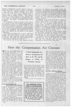
The following notes are intended simply to draw attention to the excellent structural properties of some , present-day lightweight materials, it being outside the scope of this article to discuss the actual mode of their employment. The physical properties of the.' materials may be taken as being approximately as indicated in
Table L .
Let us first compare the relative cross-sectional areas . and weights per unit length of four members, composed of the above -materials and designed to withstand the same tensile load, with those of an equivalent member in Mild steel. The ultimate tensile strength and specific gravity of the steel may be ' taken. as respectively 27.5 tons/sq. in. and 7.84.
We know that, for a given load, the necessary cresssectional area will be inversely proportional to the tensile strength, arid, Moreover, that the weight per unit length will vary directly as the specific gravity divided by the ultimate tensile strength: Denoting the cross-sectional area and weight per unit reng,th of the .steel member by respectively A and W, and adopting the appropriate constants'given-above, we may, therefore, readily derive the relative values indicated in :Table II. • From these figures We see that a great saving in weight results from the use of alternative materials in place of steel, ranging from about 59 per cent, in the case of ash, to 81 per cent, in the case of the plastic. The comparison is, however, less favourable in the ease of ash, in view of the necessary large increase in crosS-see tional area.
A similar procedure may be adopted for the purpose of cOmparing short • compression members, i.e., struts of insufficient length to exhibit bending when sub jected to a7cial cOmpression. In this instance, 'the results given in Table III are obtained, assuming the steel to possess thesame strength 'in compiession as in tension. We see, at once, that the use of. one or other of the light metals is to be " preferred, a considerable weight saving being obtainable with a comparatively small increase in cross-section.
'Turning our attention next to the subject of transversely loaded members .or beams, it may be remarked that there are many considerations in favour of designing such members expressly for the particular loading conditions involved. In mcik practical cases, ' however,
economic considerations prohibit adoption -of this procedure and render it necessary to effect a compromise.
Thus, after .the required scantlings for a given member have been calculated, it is then usually necessary to select the most suitable member from an
existing range of standard sections. Such sections, moreover, are rarely designed to give maximum efficiency under one particular type of loading, but rather to provide a fair degree of efficiency under diverse conditions: . • '''
When replacing a structural member of one material, by a member of some other material, having regard to all the factors involved, it is usually desirable to retain geometrical similarity of cross:section. That is to say, when changing from a stronger to a weaker material, it is as well to increase-all the cross-sectional dimensions by the same proportion. This procedure has, accordingly, been adopted for the purpose of the present comparisons.
The necessary calculations are, of course, a little more complex than those involved in cases of pure axial loading, and space restrictions prohibit their inclusion in the text. The. results have been arranged in convenient form for comparison in Table IV.
The symbols 8 and F have been adopted to denote
respectively the deflection and strength of the steel beam (No. 5 in the table), the deflections and strengths of the other members being shown as multiples of these constants. Beams Nos_ 1-5 are designed for equal strength, that is, to be capable of supporting the same load under • the same conditions ; Nos. 5-0" are designed for equal stiffness, that is, to exhibit the same deflection under ' identical conditions.
Examination of the table shows• that, for beams of equal strength, adoption of the plastic or AZM alloy member results in the same weight reduction, i.e., 72 per cent. The duralurnin. member gives the substantial weight reduction of 6'2 per cent. with the additional advantage of a negligible increase in cross
section. The considerable increase in area necessary-With ash would probably render adoption of this material inconvenient in many cases.
With regard to the beams' of equal stiffness, *hilst the ash member provides the greatest weight saving, the duralumin and AZM alloy members are superior from tile point of view of necessary cross-section.
In conclusion the writer desires to thank the British Aluminium Co., Ltd., James Booth and Co: (1915), Ltd., and I.C.I. (Plastics), Ltd., for much useful information provided for ,use in this article.