


Patents Completed.
Page 20
If you've noticed an error in this article please click here to report it so we can fix it.
SIX-WHEELED CIIASS1S.—De DionBouton (1907,) Ltd.—No. 1,444, dated 21st January, 1908.—This invention relates to an improved chassis for a threeaxle vehicle. The chassis comprises two independent frames (1 and 21. The frame (1) rests by means of springs (3) or any other suitable elastic connection on one of the steering axles (5), and by means of springs (4) on the driving axle (6). The second frame (2h haying the portion which covers the first frame (1) raised, rests, by means of springs (7), on the frame (1), and by means of springs (81 on the second steering axle (9). In order to maintain the two axles parallel, connecting rods (10) are secured at 11 to the frame (1), and at 12 to the frame 12). These tie rods also prevent any transverse
movement of one frame in relation to the other. They also permit the driving of one frame by the other.
DRIVING GEAR. — Poschl. — No. 10,173, dated 11th May, 1908.—The driving shaft (1) drives, through a universal joint (21, a shaft 1,31, on which is mounted a friction roller (5). The friction roller is feathered on the shaft (31, so as to be slidable thereon, and is adapted to be moved across the face of a friction disc (7) by means of suitable gearing. The friction disc (7) is carried by a vertical spindle (11), on which is mounted a worm (10), gearing with a worm wheel (12i on the driving axle. The pitch of the worm (10) is such, that the weight of the disc (7) is sufficient to cause it to turn and to recede away from the friction roller (5). The disc (7) is held in engagement with the friction roller (5) by means of a springpressed lever (131 fulcrummecl at 14. The short arm of this lever supports the vertical spindle (11( and the long arm rests upon a lever (19), which is connected to a foot pedal. It will be seen that by deoressing the lever-(19), in the usual dovmward direction, the long arm of the lever
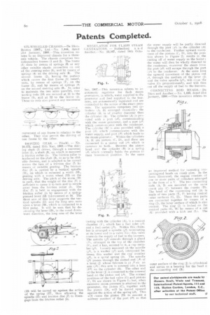
(13) will be moved up against the action of the spring (17), thus allowing the spindle (11) and friction disc (7) to disengage from the friction roller (5). REGULATOR FOR FLASH STEAM GENERATORS. — Rutherford a n d Another.—No. 22,567, dated 14th Octo
ber, 1907.--This invention relates to ran automatic regulator for flash steam generators, in which, water supplied to the generator and fuel supplied to the burners, arc automatically regulated end are controlled by the action of the steam pressure. The apparatus comprises two cylinders (A, 13) arranged co-axially; the cylinder (B) is of smaller diameter than the cylinder (A). The cylinder (A) is provided with a port (a3), communicating with the steam generator, and a port (a5) which commuaicates with the condenser. The cylinder (W is also provided with a port (1,5) which communicates with the water supply, and port (141 which leads to the steam generator. Within the oylinders A. B) are pistons (C, Di, and these are connected to a piston rod (c4) which is common to both. Between the piston head and the cylinder (B) is a spring (e3) which normally holds the pistons in their lowermost position. In the same casting with the cylinder (A), is a conical chamber (I.), which has a fuel inlet (12) and a fuel outlet (f3). Within this chamber is arranged a spindle (,,,e2) terminating at its lower end in a valve (Co ; this valve controls the supply of fuel to the burners. The spindle (g2) extends through a gland If.), arranged in the top of the chamber (F), and it has, secured td it, a cup member (g3). Looselymounted on the spindle (e-,21, is a washer (44)• and, interposed between this washer and the cup member (g3), is a spiral spring 1h1. The spindle ■ ;g2I passes through the slotted end (i6) of a lever (j) whose fulcrum is at j2 on an arm (j3) ; this arm is screwed into a boss (bit) on the cylinder (B). The other end of the lever (J) is connected to the screwed head on the piston rod (e4). The normal positions of the fuel valve (G) and pistons (C, DI are shown in Figure 1; but, when excessive steam pressure is attained in the generator, the piston (C), together with the piston (D), will be forced upward against the action of the spring (e3). This will cause the piston (D) to assume a midway position of the port (bfi) so that the water supply will be partly directed through the port 051 in the cylinder (A) to the condenser. Further upward movement of the pistons (C, D), into the position shown in Figure 2; results in the cutting off of water supply to the boiler ; the water will thert be wholly directed to the condenser, moreover the steam front the port (a3) will escape through the port :).5) to the condenser. At the same time the upward movement of the piston rod (4, through the medium of the lever (i) and the valve spindle (e2(, will close the valve (G) proportionately, and will thus cut off the supply of fuel to the burners.
CONNECTING ROD HEADS.—De Dion and Another.—No. 1,443, dated 21st January, 1908.—This invention relates to
an improved method for mounting connecting-rod heads on crank pins. In the form illustrated, the engine consists of one or more pairs of cylinders arranged in the form of a V. The two connecting rods A, 11 are mounted on the same crank pin (CI between the cranks if)). The head of the connecting rod (A) is made of two parts (E, F) having conical outer surfaces (G, II). These two parts are connected together by means of a ring 04 the inner surface of which is also conical. The ring (J1 is locked on the conical parts (G. H) by means of a nut (Kt provided with a lock nut (L). The
outer surface of the ring (J) is cylindrical and serves as a hearing for the head o: the connecting rod (B).