


CONSTANT-MESH FOUR-SPEED GEARBOX.
Page 52
Page 53
If you've noticed an error in this article please click here to report it so we can fix it.
A Novel Design on the Epicyclic Principle which Gives Remarkable Ease and Rapidity of Gear Changing.
iur-ANY attempts have been made in the past to .01_build a gearbox of the constant-mesh epicyclic type which will provide the requisite number of gear ratios and will stand pp to the high stresses and abuse inseparable from ordinary commercial usage. One of
is a four-forward-speed gearbox initially designed and the most promising which we have, seen for some time patented by Mr. Walter -Cl. Wilson, C.M.G., M.I.C.E., who, in collaboration with Sir William Tritton, was responsible for the design of the first types of Tank to be used during the war.
For a number of years this gearbox has been in the hands of the research department of Vauxhall Motors, Ltd., and recently some 20 Vauxhall private car chassis fitted with the gearbox were put on the road in order to see how they would stand up in the hands of the private user. It is from one of these cars and from Mr. Wilson's original patent specification that we have obtained the data concerning the gearbox given In this article.
Concurrently with this private car development, the gearbox has been undergoing tests in the hands of a well-known commercial vehicle building concern and we understand that it is giving promising results. On private cars it has done very well indeed, four gearboxes having each run 30,000 miles to date without a mechanical hitch of any kind, whilst the first gearbox made has covered over 45,000 miles.
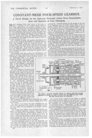
We have driven a car fitted with this gear and find its most striking features to be ease of control and silent running on each of the indirect gears. The change-speed lever is mounted at the top of the steering column and can be moved to any one of the six available positions (shown
in the photograph reproduced) DRIVING SHAFT while the car is running, without causing chante in the transmission. So soon as the clutch pedal is depressed and released, however, a change in ratio occurs corresponding to the position in which the change-speed lever has previously been set ; thus, upon the approach to a hill, the lever can be moved back from the fourth to third speed position and then, when the vehicle has slowed to a sufficient extent, it is only necessary to declutch and accelerate the engine In order to bring about the desired change down from top to third.
In respect of the control the gear resembles the one which was employed with success on Commer lorries for some years, but the gearbox is, of course, entirely different.
The Wilson gear differs from previous epicyclic designs in several important respects; thus the various ratios are obtained by compounding a number of epicyclic trains, stepping up the speed, as it were, in such a way that the relative motion between a set of planet wheels and their sun wheel is never very great. Consequently, the rate of wear is low and. the gear runs with a remarkable degree of silence.
Another important point is that the internally cut ring gears are allowed to float and are self centring. As a result, fine limits on dimensions are not required in the course of manufacture, so that the cost of making the gear is not nearly so great as might be at first
:1,1•■••
TO ENGNE DIRECT DRIVE CLUTCH
—
Igspeed ge&:s../
2,?0 • ....WO
3r.4 .
anticipated. Another feature in the design -is the use of an ingenious type of double brake band, made of springy bronze and lined with asbestos fabric, which is so mounted that it applies pure torsion without exerting any side thrust. Furthermore, a trigger device is incorporated, so arranged that wear of the 'linings is automatically taken up as it occurs, no adjustment of the brakes being required.
Careful measurement at the end of 30,000 miles has shown the amount of wear to be very slight and, by calculation, the life of the linings should be in excess of 200,000 miles. Furthermore, the automatic adjustment keeps the brake clearances constant, so enabling a high leverage and a light clutch pedal pressure to be employed. Last among the special features of the gear must be mentioned the fact that a direct drive on top is obtained.
Reference to the sectional elevation of the gear reproduced will show the arrangement of the gearwheels, this drawing, incidentally, being taken from the patent specification, so that, whilst it shows the principle employed, it does not necessarily conform with the details of construction adopted for a particular type of vehicle.
The driving shaft, coupled to the engine, is spline(' and carries two sun gears at its inner end, each of which meshes with a simple epicyclic train ; these, on the drawing, are marked "first-speed group" and "second-speed group" respectively. A disc carrying the planet pinions of the first-speed group drives a shaft which is eventually coupled to the back axle.
The engagement of first gear applies a brake to the ring gear of the first-speed group with the result that, when the sun wheel of this group is driven by the engine, the planets are carried round with an orbital motion, taking the driven shaft with them, at a speed which is, of course, considerably less than that of the driving shaft.
When second gear is engaged a brake is applied to the ring gear of the second-speed group, the previous brake being released. It will be noticed that the disc carrying the planets of this group is bolted to the ring gear of the first-speed group, the speed of which is modified by the rotation imparted to the ring gear by the planets of the second-speed group. The result is that the driving shaft turns at a higher speed than before; in other words, the two epicyclic trains are compounded to give the desired speed ratio.
When third gear is engaged the brakes previously mentioned are freed and a brake is ap plied to a drum connected with the sun wheel of the third-speed group. ,As will be seen from the sectional drawing reproduced, the ring gear of this group is part and parcel with a disc carrying the second-speed planets, whilst the third-speeil planets are fitted to a disc which is attached to
the ring gear of the second-speed group. As a
result, the motion of the third-speed planet wheels is allowed to modify the motion of the other trains of gears in such a way that the final driving shaft turtle at a higher speed than before. Finally, for top gear a direct-drive clutch is provided, the gears' then rotating en masse without relative movement.
Reverse is obtained through a fourth epicycle: train mounted at the rear end of the box, a brake being applied to the rink gear of this train. The sun wheel of this train is splined to a sleeve connected with the ring gear of the first-speed group and in this way the desired reversal of motion is caused to take place. .
The method of selecting the various brakes is very ingenious, but unfortunately, a drawing could not well be obtained from thecar which we examined. Each brake is operated by a vertical push rod, or strut, and running along the box beneath the struts is a rocking bus-bar which controls them all. This bar is held in its normal (operative) elosition by pOwerful coil springs,' but can be partially rotated away from this position by depressing the clutch pedal. The struts are Positioned by a simple camshaft which is connected through levers to the change-speed lever mounted at the top of the steering column.
To explain the action of the selector gear, suppose that the car is stationary with the gear lever in neutral and that this lever is moved to position No. 1, the result is that the camshaft holds all the struts clear of the bus-bar except the one which is connected with the first-speed brake, thisestrut being subjected to the action of the spring which forces it against the busbar.
So soon as the clutch pedal is depressed, rocking the bus-bar, strut No. 1 jumps into position and is caught by the bus-bar when the clutch pedal is released, being then pushed upwards and FO applying the first-speed brake band to its drum.
The car will then be moving forwards and we will suppose that the gear lever is shifted to position No. 2; this has the effect of putting spring tension on strut No. 2 and placing it in the " get-ready " position against the bus-bar; nothing can happen, however, until the clutch pedal is depressed. When this action takes place strut No. 1 jumps clear, whilst strut No. 2 is forced by its spring into position, where it will be caught by the bus-bar and forced upwards so soon as the clutch pedal is eleased The cone clutch which is employed to give a direct drive on top is ingenipusly operated from the bus-bar through a rack and pinion gear and is brought into action by the operation of the clutch pedal subsequent to setting the change-speed lever in the top-gear position. Placing the lever in neutral puts spring torsion upon an auxiliary trigger so arranged that when the clutch is next depressed it jumps into place, holding the bus-bar in au inoperative position and so leaving all the brakes free; the gears then rotate idly.
One of the features of the gearbox is a plunger-type oil-pump driven from an eccentric mounted at the rear end of the shaft, which delivers oil through hollow shafting to holes which distribute it to the centre of each epicyclic group. This is found to be necessary because, if the gears be simply allowed to dip into the oil, centrifugal force prevents the lubricant from reaching the teeth of the sun wheels at the centre.
As we have already explained, the gearbox must still be regarded as being in the experimental stage as ' it is not by any means ready for release to the public. However, the results already obtained are so encouraging that it is to be hoped that this novel gearbox will, before very long, be made on a commercial scale.
Whether the large number of gears employed will so raise the cost as to render difficult its inclusion in a commercial vehicle remains to be seen.