


A Variable-pitch Fan
Page 72
If you've noticed an error in this article please click here to report it so we can fix it.
• TO maintain the cooling system of an engine at the optimum operating temperature is the aim of a scheme shown in patent No. 754,852 (F. Woolley, Frank's Garage, Clarence Street, Aberavon, Port Talbot, Glamorgan). Whilst an obstructive thermostat will perform the same function, the present scheme is aimed at conserving the power absorbed by the fan when it is not required.
In the drawing, 1 is the impeller, 2 a thermostat and 3 the hub of the fan. Each blade is attached to a pinion (4) and a rack-rod (5) engages all of them. The thermostat, when expanded, shifts the rack-rod and so turns the blades to an angle giving greater air displacement.
The blades are pivoted in a state of slight aerodynamic unbalance, so that a failure of control would set them to the most effective position.
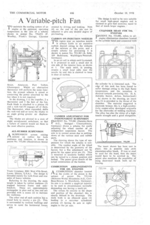
ALL-RUBBER SUSPENSION
ASUSPENSION system relying entirely on rubber for both resilience and location, is shown in patent No. 755,681 (Hendrickson Motor
Truck Company, 8001 West 47th Street, Lyons, Illinois, U.S.A.). The design is intended mainly for both front and rear axles of heavy vehicles.
Referring to the drawing, the main weight is taken by rubber cushions (1) trapped between frame and axlebrackets. These are approximately rectangular in plan and at one end are provided with a recess (2) to increase the resilience.
The other end of each cushion has a round hole to receive a pin (3). This is surrounded by resilient bushings and serves to resist the horizontal forces a34 created by driving and braking. Nuts (4) on the end of the' pin can be adjusted to give any desired degree of pre-loading.
CARBON ON INJECTION NOZZLES
THE region near an injection 'nozzle is always liable to an excessive carbon deposit owing to the richness of the mixture at this point, and a simple scheme for preventing it is shown in patent No. 753,385 (A. Stihl, 169 •Badstrasse, Waiblingcn-Neustadt, Germany).
In an air cell in which swirl is created, it is proposed to mill a small slot in one side of the injector bore, as shown at I. The main swirl, in passing, creates • a small local eddy near the nozzle tip and this is claimed to keep it clear of carbon.
CAMBER ADJUSTMENT FOR INDEPENDENT SUSPENSION
PATENT No. 755,081 (Daimler-Benz
A.G., Stuttgart Unterturkheim, Germany) shows a scheme for easily adjusting the wheel camber of an independent suspension layout. The aim is to correct errors due to settlingdown of the various steel and rubber parts.
The drawing shows the type of suspension for which the scheme is suitable. The camber angle of the wheel is determined by the geometry of the layout, but a fine adjustment can be given by the upper pivot pin (1). This is mounted in eccentric bushes which can be turned to a chosen position and locked. The patent gives details of the actual construction of the bushes.
COMBUSTION ARRANGEMENTS FOR OIL ENGINES
A COMBUSTION chamber located 4-1 in the crown of the piston is the subject of patent No. 755,144 (Motoren-Werke Mannheim A.G., CarlBenz-Straase 5, Mannheim, Germany). Its aim is to enable a single-jet injector to be used in circumstances normally demanding one having a multi-jet.
The virtues lie entirely in the shape and position of the chambei7; this is clearly defined in the drawings. The main body is an ellipsoid space (1) leading to a narrower cylindrical portion (2) having its axis at rightangles, to the jet axis.
The design is said to 'be very suitable for small high-speed engines and is claimed to give fuel economy equal to that of much larger engines.
CYLINDER HEAD FOR 'OIL ENGINES
PATENT N. 755,086, refers to oilengine eZnnbustion chambers located in the cylinder head and connected with
the cylinder by a restricted neck. The edge of this neck has been found to suffer damage owing to the high flame, temperature, and the invcntion is directed towards preventing this. (S. A. Adolphe Saurcr, Arbon, Switzerland.) As shown in the drawing, an insert ring (1) is provided in the throat of the chamber. The material suggested is electrode bronze; this is a high-conductivity copper-alloy developed originally for the electrodes of welding machines. The alloy has also the virtue of a hightensile strength and a good elongation.
The insert shown has been cast in place; this ,is possible only .with aluminium-alloy heads. If iron or steel be used for the head, then the insert would have to be screwed in. The patent also mentions the possibility of using sheet-steel heads built up by brazing.