


AN INGENIOUS STEERING GEAR.
Page 80
If you've noticed an error in this article please click here to report it so we can fix it.
A Resume of Recently Published Patent Specifications.
MIREDERICK HENRY ROYCE, in _12 specification No. 258,038, shows an improved steering arrangement which is remarkable for its simplicity and should prove a very satisfactory means of solving a problem that has been before engineers ever since the introduction of the motor vehicle.
The worm and sector has provea iThelf a useful device, but engineers have always felt that an improvement might be made here, as the surfaces in Contact, where a worm and sector are employed, are insufficient to retain lubrication and, consequently, back lash Soon develops. "
The worm-and-nut type has been tried, but has always been a trouble, as, up to now, no satisfactory means of connecting the nut to the lever of the rocking shaft has been devised. It will be seen that, whilst the nut travels in a straight line, the lever describes a curve.
• Blocks that slide in radial slots and links and other devices have been tried as a means of coupling the nut to the arm, but all such arrangements were soon found to develop backlash.
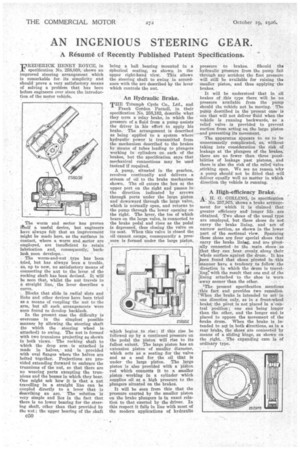
in the present case the difficulty is overcome in the simplest possible manner by allowing the steering shaft (to which the steering -wheel is attached) to swing. The nut is farmed with two trunnions projecting as shown in both views. The rocking shaft to which the drop arm is attached is made in halves, and is provided ' with oval flanges where 'the halves are bolted together. Projections are pro vided extending forward to embrace the trunnions of the nut, so that there are no wearing parts excepting the trun nions and the bosses in which they bear.
One might ask how it is that a nut travelling in a straight line can be coupled directly to a lever that is describing an are. The solution is very simple and lies in the fact that there is no lower bearing for the steering shaft, other than that provided by the nut; the upper bearing of the shaft being a ball bearing mounted in a spherical seating, as shown in the upper right-hand view. This allows the steering shaft to swing in accordance with the are described by the lever which controls the nut.
An Hydraulic Brake.
THE Triumph Cycle Co., Ltd., and
Frank Gordon Parnell, in their specification No. 258,182, describe what they term a relay brake, in which the pressure of a fluid from a pump assists the driver in his effort to apply his brake. The arrangement is described as being applied to a system where hydraulic power is transmitted from the mechanism described to the brakes by means at tubes leading to plungers working in cylinders on each of the brakes, but the specification says that mechanical connections may be used instead if required.
A pump, situated in the gearbox, revolves continually and delivers a stream of oil to the brake mechanism shown. The oil enters the box at the upper port on the right and passes in the direction indicated by arrows through ports under the large piston and downward through the large valve, which is normally open, and returns to the pump through the lower opening on the right. The lever, the toe of which bears on the large valve, is connected to the brake pedal and rises as the pedal is depressed, thus closing the valve on its seat. When this valve is closed the oil cannot escape, consequently a pres sure ia formed under the large piston, , which begins to rise; if this rise be followed up by a continued pressure on the pedal the piston will rise to its fullest extent. The large piston has an extension piston of smaller, diameter, which acts as Er seating for the valve and as a seal for the oil that is under the large piston. The large piston is also provided with a pigton rod which connects it to a smaller piston working in a cylinder which supplies oil at a high pressure to the plungers situated on the brakes.
It will be seen from this that the pressure exerted by the smaller piston on the brake plungers is in exact relation to that exerted by the driver. In this respect it falls in line with most of the modern applications of hydratdic
pressure to brakes. Should the hydraulic pressure from the pump fail through any accident the foot pressure will still be available for raising the smaller piston, and thus applying the brakes.
It will be understood that in all brakes of this type there will be no pressure available from the pump should the vehicle not be moving. The pump described in the present ease is one that will not deliver fluid when the vehicle is running backwards, so. a relief valve is provided to prevent suction from acting on the large piston —and preventing its movement.
The apparatus appears to us to be unnecessarily complicated, as, without taking into consideration the risk of leakage at the plungers of the brakes, there are no fewer than three possibilities of leakage past pistons, and there is also the risk of the relief valve sticking open. We see no reason why a pump should not be fitted that will deliver equally well no matter in which direction the vehicle is running.
. A High-efficiency Brake.
A. H. G. GIRLING, in specification No. 257,975, shows a brake arrangement for which it is claimed that greater efficiency and longer life _ are 'obtained. -Two 8hoes of the usual type are employed, but these shoes do not 'carry the brake lining, and are of narrow section, as shown in the lower part of the sectional view. Spanning these shoes are four special shoes that carry the brake liniag, and are 'pivot'ally connected to the main shoes So that they can _bear evenly_ along their whole surface against the drum.• It has been found that shoes pivoted in ...this Imanner have a tendency to follow the 'direction in which the drum is travel;Iing,• with the result that one end of the lining attached to the shoe is worn iaway sooner than the other.
'The present specification mentions this fact and provides two remedies. When the brake is intended to act in 'one direction_ only, as in a front-wheel brake'; the pivot is not placed in a'central position one end being longer than the other, and the longer end is placed to oppose the movement of the brake drum. When the brake is intended to agt in both directions, as_ in a rear brake; the-shoes' are connected by means' of a eliding binge, as shown' on the right. The expanding cam is of ordinary type.