


SPRINGS FOR VARYING LOADS.
Page 28
If you've noticed an error in this article please click here to report it so we can fix it.
A Résumé of Recently Published Patent Specifications.
Toprovide a spring which is suitable for use with such vehicles as buses and chars-a-banes, in which the loads vary continually andwhere undue rolling cannot be permitted, has always been a problem.
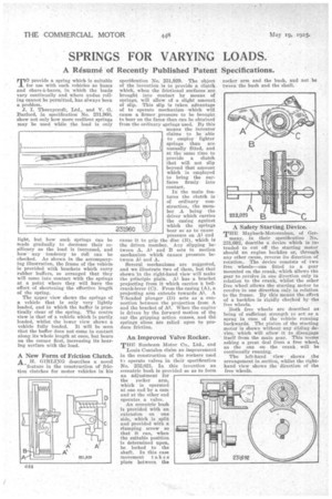
J. I. Thernycraft, Ltd., and V. G. Barford, in specification No. 231,960, show not only how more resilient springs may be used while the load is only
but how such springs can be made gradually to decrease their resiliency as the load is increased, and how' any • tendency to roll can be checked. As shown in the accompanying illustration, the frame of the vehicle is provided with brackets which carry rubber buffers, so arranged that they will come into Contact with the springs at a point where they will have the effect of shortening the effective length of the spring.
The upper view shows the springs of a vehicle that is only very lightly loaded, and in which the buffer is practically clear of the spring. The centre view is that of a vehicle which is partly loaded, whilst the lower view shows a vehicle fully loaded. It will be seen that the buffer does not come in contact along its whole length at OTICC, but bears an the corner first, increasing its bearing surface with the load.
A New Form of Friction Clutch. A H. GIRLP.,,TG describes a novel 'feature in the construction of friction clutches for motor vehicles in his specification No. 231,929. • The object of the invention: is to provide a clutch which, when the frictional surfaces are brought into contact by means of springs, will allow of a slight amount of slip. This slip is taken advantage of to operate mechanism which will cause a firmer pressure to be brought to bear on the faces than can be obtained from the ordinary, springs used. By this means the inventor claims to be able to : employ lighter springs than are unsually fitted, and at the-same time to provide a clutch that will not slip beyond that amount which is employed to bring the surfaces firmly into contact.
In the main features the clutch is of ordinary construction, the member A being the driver which carries the casing against which the springs hear so as to cause pressure on AL and cause it to grip the disc (B), which is the driven member. Any slipping between A, Al and B Sets in motion mechanism which causes pressure between Al and A.
Several mechanisms are suggested, and we illustrate two of them, but that shown 'in the right-hand view will make the principle plain. AlhasP a bracket projecting from it which carries h bellcrank-lever (C). From the easing (A), a projecting arm extends towards Al. A T-headed plunger (D) acts as a connection between the projection from A and the bracket of A2. When the engine is driven by the forward motion of the car the gripping action ceases, and the springs alone Aro relied upon to produce friction.
An Improved Valve Rocker.
THE Sunbeam Motor Co., Ltd., and
Louis Coatalen claim an improvement in the construction of the rockers used t3 operate valves in their specification No. 232,021. In this invention an eccentric bush is provided so as to form an adjustment for the rocker arm, which is operated at one end by a cam and at the other end operates a valve.
An eccentric bush is provided with an extension on one side, which is split and provided with a clamping screw so that it can, when the suitable position is determined upon, be locked to the shaft. In this case movement takes place between the rocker arm and the bush, and not be tween the bush and the shaft.
A Safety Starting Device.
THE Maybach-Motorenbau, of Ger many, in their specification No. 231,692, describe a. device which is intended to cot off the starting motor should an engine backfire or, through any other cause, reverse its direction of rotation. The device consists of two free wheels—one fitted to a gear mounted on the crank, which allows the gear to revolve in one direction only in relation to the crank, whilst the other free wheel allows the starting motor to revolve in one direction only in relation to the frame. By this means the effect of a backfire is rigidly checked by the free wheels.
Both free wheels are described as being of sufficient strength to act as a spriv• in case of the vehicle running backwards. The pinion of the starting motor is shown without any sliding device, which will allow it to disengage itself from the main gear. This seems asking a great deal from a free wheel, as the one on the crank, will be continually running,
The left-hand view shows As arrangement in section, whilst the righthand view shows the direction of the free wheels.