


Assisted Clutch Pedal
Page 68
If you've noticed an error in this article please click here to report it so we can fix it.
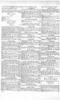
ASPRUNG pedal which allows a clutch with a heavy action to be released with about half the normal effort is shown in patent No. 826,459. (Daimler-Benz A.G., Stuttgart-Unterttirkheim, Germany.) A spring mechanism that changes the direction of its force by rocking over dead centre is employed.
Referring to the drawing, the pedal is pivoted at the point 1 and is loaded by a stretched spring (2) towards its pivot; the spring being attached to the point 3. In operation, the spring creates a slight opposition to initial movement but, as the pedal is further depressed, the spring passes over the centre, adding its force to he effort of the driver. This position is AN AUTOMATIC GEARBOX DATENT No. 826,655 describes an
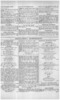
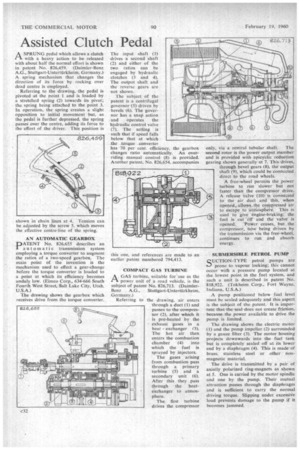
automatic transmission system employing a torque converter to augment the ratios of a two-speed gearbox. The main point of the invention is the mechanism used to effect a gear-change before the torque converter is loaded to a point at which its efficiency becomes unduly low. (Eimco Corp., 634-666 South Fourth West Street, Salt Lake City, Utah, U.S.A.) The drawing shows the gearbox which receives drive from the torque converter.
The input shaft (1) drives a second shaft (2) and either of the two ratios can be .engaged by hydraulic clutches (3 and 4). The output shaft and the reverse gears are not shown.
The subject of the patent is a centrifugal governor (5) driven by bevels (6). The governor has a snap action and operates the hydraulic control valve (7). The setting is such that if speed falls below that at which the torque converter .
has 70 per cent, efficiency, the gearbox changes ratio automatically. An overriding manual control (8) is provided. Another patent, No. 826,654, accompanies
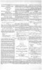
AGAS turbine, suitable for use as the power unit of a road vehicle, is the subject of patent No. 826,713. (Daimler
Ben z A.G.. Stuttgart-Unterttirkheirn, Germany.) Referring to the drawing, air enters through a duct (1) and passes to the compressor (2), after which it is pre-hcated by the exhaust gases in a heat exchanger (3). The hot air then enters the combustion chamber (4) into which the fuel is sprayed by injectors.
The gases arising from combustion pass through a primary turbine (5) and a secondary unit (6). After this they pass through the heatexchanger to atmosphere.
The first turbine drives the compressor only, via a central tubular shaft. The second rotor is the power output member and is provided with epicyclic reduction gearing shown generally at 7. This drives, through bevel gears (8), the output shaft (9), which could be connected direct to the road wheels.
"A free-wheel permits the .power turbine to run slower but not faster than the compressor. drive. A release valve (10). is connected to the air duct and this, when opened, allows, the compressed air to escape. to atmosphere. This is used to give engine-braking; the fuel is cut off and the valve is
opened. Power ceases, but _ the compressor, how being driven by the transmission via the free-wheel, continues to run and absorb energy.
SUBMERSIBLE PETROL PUMP
RUCTION-TYPE petrol pumps are *--) prone to vapour locking; this cannot occur with a pressure pump located at the lowest point in the fuel system, and such a unit is described in patent No. 818,922. (Tokheim Corp., Fort Wayne, Indiana, U.S.A.)
A pump positioned below fuel level must be sealed adequately and this aspect is the subject of the patent. It is important that the seal does not create friction, because the power available to drive the pump is limited.
The drawing shows the electric motor (1) and the pump impeller (2) surrounded by a gauze filter (3). The motor housing projects downwards into the fuel tank but is completely sealed off at. its lower end by a diaphragm (4). This is made of brass, Stainless steel or other nonmagnetic material.
The drive is transmitted by a pair of axially polarized ring-magnets as shown at 5. One is carried by the motor spindle and one by the pump. Their mutual attraction passes through the diaphragm and is sufficient to carry the normal driving torque. Slipping under excessive load prevents damage to the pump if it becomes jammed.