


Workshop ways
Page 31
Page 32
Page 33
If you've noticed an error in this article please click here to report it so we can fix it.
Getting off to a ood start
IN THE FIRST article in this series on the electrical system we took a look at lighting circults and how to check them. In this instalment we're running through the routines for diagnosing faults in starting systems — with particular emphasis on light commercials.
Once again, we asked the technical service department of Joseph Lucas (Sales and Service) Ltd to set out the routine to be followed and the equipment they recommend. But before tackling fault-finding, let's just run through how the typical starting system is designed to work.
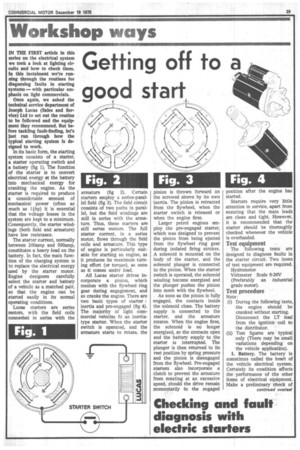
In its basic form, the starting system consists of a starter, a starter operating switch and a battery (fig 1). The function of the starter is to convert electrical energy at the battery Into mechanical energy for cranking the engine. As the starter is required to produce a considerable amount of mechanical power (often as much as lihp) it is essential that the voltage losses in the system are kept to a minimum. Consequently, the starter windings (both field and armature) have low resistance.
The starter current, normally between 200anip and 500amp, constitutes a heavy load on the battery. In fact, the main function of the charging system is to replace the electrical energy used by the starter motor. Engine designers carefully select the starter and battery of a vehicle as a matched pair, so that the engine can be started easily in its normal operating conditions.
Lucas starters are series motors, with the field coils conneoted in series with the armature (fig 2). Certain starters employ a series-pazallel field (fig 3). The field circuit consists of two paths in parallel, but the field windings are still in series with the armature. Thus, these starters are still series motors. The full starter current, in a series motor, flows through the field coils and armature. This type of engine is particularly suitable for starting an engine, as it produces its maximum turning effort (or torque), as soon as it comes under load.
All Lucas starter drives incorporate a pinion, which meshes with the flywheel ring gear during engagement, and so cranks the engine. There are two basic types of starter : inertia and pre-engaged (fig 4). The majority of light commercial vehicles fit an inertiatype starter. When the starter switch is operated, and the armature starts to rotate, the pinion is thrown forward on the screwed sleeve by its own inertia. The pinion is retracted from the flywheel, when the starter switch is released or when the engine fires.
Larger petrol engines employ the pre-engaged starter, which was designed to prevent the pinion from being ejected from the flywheel ring gear during isolated firing strokes. A solenoid is mounted on the body of the starter, and the solenoid plunger is connected to the pinion. When the starter switch is operated, the solenoid winding become energised and the plunger pushes the pinion into mesh with the flywheel.
As soon as the pinion is fully engaged, the contacts inside the solenoid close. The battery supply is connected to the starter, and the armature rotates. When the engine fires, the solenoid is no longer energised, so the contacts open and the battery supply to the starter is interrupted. The plunger is then returned to its rest position by spring pressure and the pinion is disengaged from the flywheel. Pre-engaged starters also incorporate a clutch to prevent the armature from rotating at an excessive speed, should the drive remain momentarily in the engaged position after the engine has started.
Starters require very little attention in service, apart from ensuring that the main leads are clean and tight. However, it is recommended that the starter should be thoroughly checked whenever the vehicle is overhauled.
Test equipment
The following tests are designed to diagnose faults in the starter circuit. Two items of test equipment are required.
Hydrometer Voltmeter Scale 0-20V (Preferably an industrial grade meter).
Test procedure
Note: (1) During the following tests, • the engine should be cranked without starting. Disconnect the LT lead from the ignition coil to • the distributor.
(1i) Test figures are typical only (There may be small variations depending on • the vehicle application), I. Battery. The battery is sometimes called the heart of the vehicle electrical system. Certainly its condition affects the performance of the other items of electrical equipment. Make a preliminary check of the battery connections. Ensure they are clean and tight. Remove any oxidation from the battery posts and cable lugs, and smear them with petroleum jelly before remaking the connections. Then, use the hydrometer to check the state of charge. All cell readings should be 1.230 or more, indicating that the battery is at least 70 per cent charged. Further, the difference between any two cell readings should not exceed 40 points. If the cell readings are lower than 1.230, the .battery should be re-charged from an external source, using a battery charger, not a trickle charger.
2. Connections. All connections in the starter circuit must make good electrical contact. Pay special attention to the earth connections. Check that the bonding straps between the engine, chassis and body of the vehicle are in good condition and make metal-to-anetal contact. Any earth braids, which are frayed, must be replaced.
3. Battery to voltage.on load. Then, the voltage across the battery is checked, while the starter is cranking the engine. The voltmeter reading should be approx 10.5V—for inertia starters 10V—for pre-engaged starters (These readings are typical only, there are many variations depending on the vehicle application.) If the reading is satisfactory, proceed to Test 4.
However, if the voltmeter reading is considerably lower, the battery should be rechecked by means of the hydrometer. If the battery is now shown to be less than 70 per cent charged, the test should be repeated with a substitute battery of equivalent capacity. If the engine is not being cranked by the starter, check the solenoid and the connections. First, check whether you can hear the solenoid operating. Then, check the starter itself. Measure the voltage at the starter main terminals, when the starter switch is being operated. If the reading obtained is battery voltage, the starter is probably faulty and should be removed for bench test. However, if a zero reading is obtained, the solenoid or the wiring is faulty.
4. Voltage at solenoid operating terminal. Next, the voltmeter is connected between the solenoid operaJting terminal and a good earth point. If the reading is the same as was obtained 'in the previous test, you should proceed to Test 5.
However, if the reading is considerably lower, there is probably excessive voltage drop in the circuit between the battery and the solenoid, so the ignition/starter switch together with all the cables and connections should he checked systematically.
5. Voltage at starter on load. Then, the voltage at the starter is checked. The voltmeter is connected between the starter main insulated terminal and a good earth point. When the engine is being cranked, the voltmeter reading should be not more than 0.5V below the readings obtained in Tests 3 and 4.
If the reading is correct, it confirms that the starter circuit is satisfactory. But, if the reading is more than 0.5V below the obtained in Tests 3 and 4, it proves •that there is excessive voltage drop in the insulated line or the earth line.
6. Voltage drop : insulated line. To measure the voltage drop in the insulated line, the voltmeter is connected between the starter main terminal and the battery insulated terminal. When the starter switch is operated, the voltmeter reading should be approx zero. In that case, it proves that the voltage drop along the insulated line is not excessive. It will, therefore, be necessary to check the earth line (Test 8).
If, however, the reading is more than 0.5V, there is excessive voltage drop in the insulated line, either across the solenoid contacts, or in the cables and connections. It will, therefore, be necessary, to proceed to Test 7.
7. Voltage drop, solenoid contacts. The voltmeter is then connected across the solenoid contacts. When the starter switch is operated, and the engine is being cranked, the voltmeter reading should be approximately zero.
If it exceeds 0.25V, the solenoid should be replaced. However, if the reading is less than 0.25V, it confirms that the solenoid is operating satisfactorily. Consequently, the cause of high voltage drop must be in the cables and connections. The connections in the insulated line are then checked, being cleaned and remade, as necessary. Any damaged leads should be replaced.
After the wiring and connections have been rectified, Test 6 should be repeated to ensure that the voltage drop along the insulated line is within permissible limits.
8. Voltage drop : earth line. Finally, check for excessive voltage drop along the earth line. The voltmeter is connected between the battery earth terminal and the starter mounting point. Then, the starter switch is operated. (Ensure that the engine is being cranked). The voltmeter reading should be approximately zero. If, however, the reading is above 0.25V, all earth connections should be checked. Ensure they make clean metalto-metal contact. Examine the condition of the bonding strap, and replace, if frayed.