


"A ; .Loading-cum-Tipping Vehicle A VEHICLE designed for digging its own loqd
Page 52
If you've noticed an error in this article please click here to report it so we can fix it.
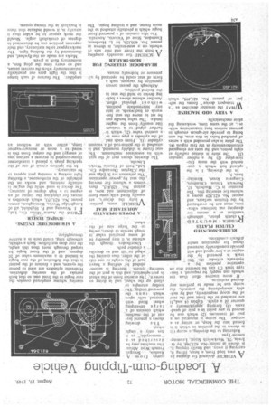
from, a heap, lifting it, carrying it away, and finally 'tipping it, is shOwn in patent-No. 621,3.44. by G Irwin, 73. Warkworth Street, Leatnington-on-Tyne = Referring to the drawing, a scoop (1) is shown in the position in which it is forced into the heap, or actingas a scraper. The Scoop is mounted on a pair of trunnions (2) which can be moved to any point in a pair of qUadrants 13) forming approxima4ely a quartet ict a .circle. ,'C4,1ales (4 and,5) are attached to the front and the rear of the scoop respectively, and by suitably .manipulating the controls, the scoop can be made to perform any desired evolution.
If more tractive effort than the wheels can supply be required, a linktype track (7) can be lowered into an operative position by a hydraulic cylinder (8). Tlfe track is powered by the engine at a ,low speed and will provide considerably increased thrust for operation under difliculi conditions.
RUBBER-MOUNTED CLUTCH PLATES
RLIBBER MOUNTED
. clutch plates, -although excellent as a .means for damping out torsional vibration, must not be overheated by the friction surfaces, and patent No. 621,929 shows a scheme for ensuring this. The patentee is C. Macbeth, 67, Norwich Union Chambers, , Congreve Street, Birming ham, 3. •
In the drawing, 1 is the splined hub which is connected with the main friction-plate (2) by a rubber annulus
(3). The plate is slotted radially at eight points, and the slots are elongated circumferentially In the free region (4). The plate is also, provided with a series of punched holes in this area, the aim being to provide air-spaces enough to prevent serious heat transmission withot t, at the Same time, weakening the plate •mechanically.
A VERY ODD MACHINE
WHAT the inventor describes as "a VT transport device" forms the subjecl of patent No. 621;495, which comes f.r o m A .
.Raulais, . Senegal, French 'West Africa. The machine may be described as a "
monocycle," as it has only a,' single wheel. . • 1h e drawing shows a general layout of the machine.
which consists ofa I arge enveloping
wheel fitted with internal railstipon which rim n's the powered-trolley, The; trolley • attempts to' climb up the wheel, and in doing so turns it.. The exterior form of the wheel is part-spherical,' and this is part of the steering. system. -• Steering is accomplished by shifting a heavy part' of the. weight to one side or the other, thus causing the wheel to 'tilt and so describe a circular path.
Unorthodox though the scheme is, it may possibly be of some practical valne in rough terrain or desert; owing to the 'large size or the ivheel. •
. A POWER-OPERATED ADJUSTABLE SEAT X fEHICLE seats, partialV larly the driver's, are usually fitted -with. same form' pt adjustment, and -now, in .patent No. 620,815_,_ there -comes a. 'scheme for moving t the. seat by‘poWer -operation. -The patentees are S. Edge and the .Clayton Dewandre Co., Ltd., both of Titantic Works, Lincoln.
The drawing shows, part of the seat, with its asseiciated mechanism. The seat frame is slidably mounted, _and .is attached to theptisto,n-rodof a Ain-un-:In cylinder (I) . rpm each end.. 'of the cylinder a pipe runs to' a control valve' (2), whieh further -piped = te b Vadfium line usually from the engine intake. The valve handle, can be set to move the seat forwards or backwards, or into any intermediate , position, withon t' physical effort. Another scheme shows a locking device to hold the seat in the desired, position.
'Although the patent covers operation by vacuum, such a form of seat could be operated pressure or hYdraulic means.
REAR-BOGIE STEERING FOR . SEMI-TRAILER
ASCHEME for steerably coupling both, the front and rear sets vf wheels on -a semi-trailer, is shown in patent NO. 620,126, by L. Hardman, Essendon, State of Victoria, Australia.
The idea consists of a powered front bogie which is pivotally attached to the main frame, and a trailing bogie. The steering' scheme employed couples the rear bogie to the front one, so that both partake of the steering deflection. Hydraulic cylinders are used to power the system, and a feature of the patent is that the deflection of the rear bogie is limited to a maximum value of 20 degrees, and if the front bogie be turued through more than this angle, the rear does not follow. Such a vehicle, although lohg, could turn in a narrow thoroughfare.
A SI.ROBOSCOPIC FMlNl
• • XI M , TEStEit •
CROM the Austin' albior Co., Ltd., I. Weaving and F. Hightield, all of Longbridge Works, Birmingham, comes patent No. 621;353, which describes a means for checking the timing of an engine to a high degree of accuracy. The device is used while the eng:ne is actually running, and works on the principle of the stroboscope, a flashing light making a running part appear to be stationary..
In' the ignition circuit of one of the sparking plugs is placed a transformer (loose-coupled to prevent a serious loss of energy) and the output from this is .
wired-to a neon or mercury-vapour lamp, ..either with or without an amplifier. The feature of such lamps is that thelight goes out practically instantaneously when the current ceases, , and so every time the plug fires, a momentary flash is given.
Marks are made on the flywheel, and illuminated by the flashing light. The marks appear to be stationary, and their apparent position can be determined in degrees of crankshaft angle. Should . the mark appear to be wider than it actually is, it would indicate that there is backlash in the timing system.