


A 1 5-IN. TYRE THE MAKING
Page 54
Page 55
Page 56
Page 57
If you've noticed an error in this article please click here to report it so we can fix it.
The Marvels of the Production of the Largest Size of Tyre at Present in (.19e, Fully Explained and Clearly Illustrated In Convenient Stages, We Conduct Our Readers Around Fort Dunlop, the Gigantic Headquarters of the Dunlop Rubber Co., Ltd.
IT has been predicted from time to time that in the near future all vehicles on the roads will be mounted on pneumatic tyres, which would enable road makers to consider the problem of their construction from an entirely new angle; giving us better and more durable foundations and surfacings.
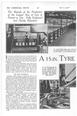
That the general use of pneumatic tyres, even for the heaviest classes of vehicle, is not far off may be judged by the fact that The Dunlop Rubber Co., Ltd., are now engaged at Fort Dunlop in making tyres of a size and weight-carrying capacity which would have been thought impossible only a few years ago. The tyre to which we refer is known as the 15.00-in., and it is intended to carry a load of 94 cwt. per tyre with safety.
The Cord Foundation.
'Although rubber forms an important part in the nanufacture of a successful pneumatic tyre, it is by no means the only material the selection and manipulation of which have to be considered with the greatest care. This will be readily understood when one realizes that all the stresses due to the internal air pressure and those resulting from tyre flexion have to be borne by scientifically constructed cotton-cord components which form the tyre casing. These cords are specifically designed after a study of the stresses peculiar to a tyre, and are made in the Dunlop Cotton Mills at Rochdale, Lancashire—the largest cotton mills under one roof.
In a tyre of this type, cotton represents approximately 16 per cent. by weight.
The cotton hairs, from which the cords are made, are a complicated botanical structure ; in appearance representing a flattened, twisted ribbon-like tube having a diameter of approximately one fifteenhundredth of an inch and a length of 1i in. These hairs are spun into a yarn of such fineness that a tyre of this size will contain as much as 600 miles. The spun yarn is combined into a complex assembly, generally known as a 15-fold cord.
The process briefly consists of arranging groups of spun threads in a certain manner and giving each group a pre-determined number of twists per unit length, under accurately controlled conditions. Three groups of five threads are used, each group being twisted in a
c32 .
direction similarto that of the spun yarn. Three of the groups, each comprised of five of the spun yarns, are then combined and twisted in a direction opposite to that of the spun yarn. It is of supreme importance that the tension of each yarn should be known, and controlled during the process of twisting. The relation of twists at each operation must be scientifically balanced so as to build into the construction the characteristics which will give the maximum mileage for a unit weight of cotton.
In one ply of rubberized fabric no fewer than 25 such cords lie side by side in 1 in. width. Such a strip of cord is capable of bearing a stress of approximately 400 lb., so that it is not difficult to realize that in a tyre of this size, which has as many as 20 layers of cord, there is an ample impact and fatigue strength, even when allowance is made for continual wear.
Where the Cords are Rubberized.
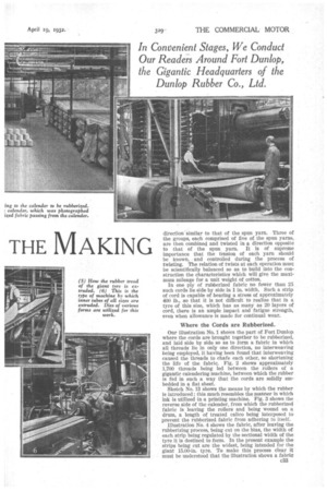
Our illustration No. 1 shows the part of Fort Dunlop where the cords are brought together to be rubberized, and laid side by side so as to form a fabric in which all threads He in only one direction, no interweaving being employed, it having been found that interweaving caused the threads to chafe each other, so shortening the life of the fabric. Fig. 2 shows approximately 1,700 threads being led between the rollers of a gigantic calendering machine, between which the rubber is fed in such a way that the cords are solidly embedded in a fiat sheet.
Sketch No. 13 shows the means by which the rubber is introduced ; this much resembles the manner in which ink is utilized in a printing machine. Fig. 3 shows the reverse side of the calender, from which the rubberized fabric is leaving the rollers and being wound on a drum, a length of treated calico being interposed to prevent the rubberized fabric from adhering to itself.
Illustration No. 4 shows the fabric, after leaving the rubberizing process, being cut on the bias, the width of each strip being regulated by the sectional width of the tyre it is destined to form. In the present example the strips being cut are the widest, being intended for the giant 15.00-in. tyre. To make this process clear it must be understood that the illustration shows a fabric composed of cords, all running in a vertical direction, and merely held in contact by adhesion.
An endless cable runs over pulleys at the ends of the anglewise beam, and a small blade attached to the cable separates the strip from the main lengtlr of the fabric. One of these strips of oneway threads is laid around a drum of the required diameter, all the threads lying at an angle with the axis of the drum; a second layer of threads is then laid over the first one, all its threads lying crosswise to those of the first layer. The endless band thus formed is then removed from the drum, and a series completed ready for use in the building up of a tyre.
The manufacture and technique of the rubber portions of giant and other tyres is perhaps of even more importance than that of the textile fabric. After the particular grades of raw rubber most suitable for the purpose have been determined, it is necessary to cut each bale into several pieces, and for each batch that goes to the mastication process portions are taken from a number of bales, the reason for this being that rubber is an organic substance and each bale may have its own particular characteristics, so by completely mixing them a uniform blend can be obtained.
To those unfamiliar with the subject it may seem that any substance introduced into the rubber may be regarded as an adulterant or an attempt to reduce the cost. This, however, is far from the truth, as many of the substances necessary for the production of a successful tyre are far more costly than rubber. The requisite characteristics of the rubber which forms a tyre may be roughly said to be as follow :--resistance to abrasion; resistance to cutting by sharp edges; toughness; resistance to the effects of sunlight, air, etc.; resistance to permanent deformation under load, and resistance to the generation of heat caused by repeated flexing.
e34 These and many other points have to be considered in the manufacture, and only thorough investigation by experts of the effect of the introduction of certain chemical substances, and by prolonged comparative trials, can be relied upon for the production of a tyre which will give maximum service.
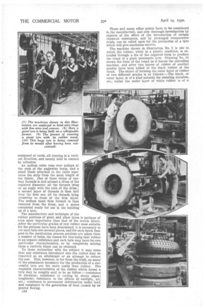
The machine shown in illustration No. 5 is one in which the rubber, while in a plastic condition, is extruded through a die of the required form to produce the tread of a giant pneumatic tyre. Drawing No. 14 shows the form of the tread as it leaves the extruding machine, and after two layers of rubber of another quality have been added to the black rubber of the tread. The object of forming the outer layer of rubber of two different grades is as follows :—The black, or outer layer, is of a kind suitable for resisting abrasion, etc., whilst the under layer of white rubber is of a
nature, forming a soft adhesive cushion between the harder rubber and the cotton fabric, its object being mainly to reduce the amount of heat generated by flexion.
In No. 6 we show the kind of machine in which the air tubes of pneumatic tyres are made by extrusion, under great pressure, through an outer die and over an internal plate, the difference between the two diameters determining the thickness of the tube. This class of machine is employed for the making of air tubes of all kinds, but in the case of those for giant tyres a much larger die is required, and the inner plate is set slightly eccentric to the outer die, so that the tube shall be slightly thicker on the outside to allow for the bending that is necessary to enable it to fit the wheel curve.
The wires used in the edges of giant tyres are of special high-tensile steel carefully protected against
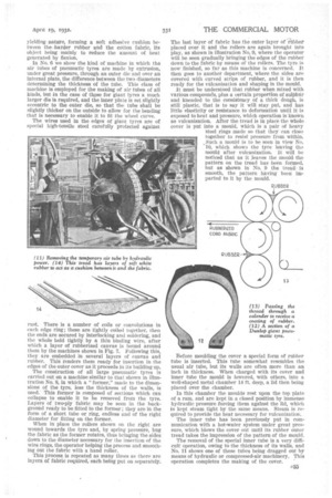
rust. There is a number of coils or convolutions in each edge ring; these are tightly coiled together, then the ends are secured by interlocking and soldering, and the whole held tightly by a thin binding wire, after which a layer of rubberized canvas is bound around them by the machines shown in Fig. 7. Following this, they are embedded in several layers of canvas and rubber. This senders them ready for insertion in the edges of the outer cover as it proceeds in its building up. The construction of all large pneumatic tyres is carried out on a machine similar to that shown in illustration No. 8, in which a "former," made to the dimensions of the tyre, less the thickness of the walls, is used. This former is composed of sections which can collapse to enable it to be removed from the tyre. Layers of two-ply fabric may be seen in the background ready to be fitted to the former ; they are in the form of a short tube or ring, endless and of the right diameter for fitting on the former.
When in place the rollers shown on the right are wound towards the tyre and, by spring pressure, hug the fabric as the former rotates, thus bringing the sides down to the diameter necessary for the insertion of the wire rings, the operator helping the process and smoothing out the fabric with a hand roller.
This process is repeated as many times as there are layers of fabric required, each being put on separately.
The last layer of fabric has the outer layer of /libber placed over it and the rollers are again brought into play, as shown in illustration No 9, where the operator will be seen gradually bringing the edges of the rubber down to the fabric by means of the rollers. The tyre is now finished, so far as this machine is concerned. It then goes to another department, where the sides are covered with curved strips of rubber, and it is then ready for the vidcanization and shaping in the mould.
It must be understood that rubber when mixed with various compotmds, plus a certain proportion of sulphur and kneaded to the consistency of a thick dough, is still plastic, that is to say it will stay, put, and has little elasticity or resistance to deformation until it is exposed to heat and pressure, which operation is known as vulcanization. After the tread is in place the whole cover is put into a mould, which is a pair of heavy Steel rings made so that they can close together to resist pressure from within. Such a mould is to be Seen in view No. 10, which shows •the tyre leaving the mould after vulcanization. It will be noticed that as it leaves the mould, the pattern on the tread has been fornied, but as shown in No. 9 the tread. is smooth, the pattern having been imparted to it by the mould.
Before moulding the cover a special form of rubber tube is inserted. This tube somewhat resembles. the usual air tube, but its walls are often more than an inch in thickness. When charged with its cover and inner tube the mould is towered, with others, into a well-shaped metal chamber 14 ft. deep, a lid then being placed over the chamber.
In this chamber the moulds rest upon the top plate of a ram, and are kept in a closed position by immense hydraulic pressure forcing them against the lid, which is kept steam tight by the same means. Steam is required to provide the heat necessary for vulcanization.
The inner tube has been previously put in communication with a hot-water system under great pressure, which blows the cover out until its rubber outer tread takes the impression of the pattern of the mould.
The removal of the special inner tube is a very difficult operation, owing to the thickness of its walls, and No. 11 shows one of these tubes being dragged out by means of hydraulic or compressed-air machinery. This operation completes the making of the cover. '