


Ball Bearings An Analysis.
Page 2

Page 3
If you've noticed an error in this article please click here to report it so we can fix it.
By Herbert Guthrie.--concluded from page 96.
For the heavy types of wheel-bearings, under these conditions, no less than four rings of balls are required. Two, as before, to cairy the weight, and two others to take the longitudinal thrust in either direction. Such a bearing is shown by Fig. it. The two outside rings (dd) carry the weight, which is all directly downwards, from axle to hub.Thus arranged, the balls do the single duty of anti-friction rollers, and are very simp:e to arrange. A plain, hard steel hush (b) is driven on the axle to take the wear of the balls. These balls run round the axle in the orbit co, and revolve on the axis a, which should be, and is, practically, a true roll. Likewise, to take the wear, the hub is fitted with two hard steel rings (gg), one at each end of the bush. To resist the longitudinal thrusts, or side shocks to the wheel, a central collar (f) is arranged on the hush, and, between this collar and the hub rings (gg), two other sets of balls are arranged. Now, these thrust rings do exactly similar duty to that already reviewed and represented by Fig. 8, in the previous article, and the same remarks, to a large extent, are applicable. As to the running of these balls when out of service, they simply roll loosely round, either in the bottom or top of the V formed by the concave tracks ; but, when in action, the balls will be squeezed between two concave tracks, and will act similarly to the common bicyclebearing balls, already described and shown (Fig. to). The balls, under pressure, will always try to roll outwards at a tangent, and will only be restrained from this by their slightly climbing the inclines, and doing a certain amount of spinning as well as rolling. These thrust balls, how
ever, only do intermittent work, and are constantly jumping in and out of duty, which must reduce their wearing qualities.
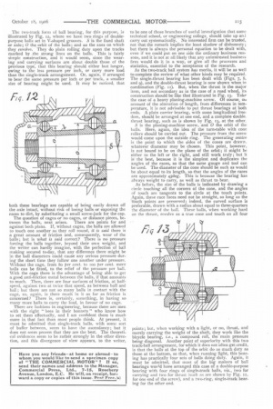
The two-track form of ball bearing, for this purpose, is illustrated by Fig. 12, where we have two rings of doublepurpose balls set in V-shaped grooves. S is the fixed shaft or axle; 0 the orbit of the balls ; and aa the axes on which they revolve. They do plain rolling duty upon the tracks marked by the strong lines on the balls. This is fairly simple construe Lion, and it would seem, since the wearing and carrying surfaces are about double those of the previous type, that this bearing should either last longer, owing to the less pressure per inch, or carry more load than the single-track arrangement. Or, again, if arranged to bear the same pressure per inch or per track, a smaller size of bearing might be used. It may be noticed, that
both these bearings are capable of being easily drawn off the axle intact, without risk of losing balls or exposing the races to dirt, by substituting a small screw-jack for the cap.
The question of cages or no cages, or distance pieces, between the balls, next arises. There are points for and against both plans. If, without cages, the balls are allowed to touch one another as they roll round, it is said there is a great amount of friction and, consequently, wear of the balls; but is what is said correct? There is no pressure forcing the balls together, beyond their own weight, and the writer can hardly imagine, with the perfection of ball making secured to-day, that any difference there might be in the ball diameters could cause any serious pressure during the short time they follow one another under pressure. Without the cage, from 8o per cent. to ioo per cent, more balls can be fitted, to the relief of the pressure per ball. With the cage there is the advantage of being able to get a good anti-friction metal between the balls, if that amounts to much. Then, there are four surfaces of friction, at halfspeed, against two at twice that speed, as between ball and ball; but there are not so many balls in contact with the cage, so, again, is there much in it as far as friction is concerned? There is, certainly, something, in having so many more balls to carry the load, in favour of no cage. There are fashions in engineering, because there are men with the right "bees in their bonnets" who know how to set them effectually, and I am confident there is much more in that fact than most people think. At present, it must be admitted that single-track balls, with some sort of buffer between, seem to have the ascendancy; but it does not seem proven that they are the best. The theoretical evidences seem to be rather strongly in the other direction, and this divergence of view appears, to the writer,
to be one of those branches of useful investigation that some technical school, or engineering college, should take up ani carry out systematically. No interested firm can be trusted, not that the remark implies the least shadow of dishonesty; but there is always the personal equation to be dealt with, even if we could put on one side the ordinary business reasons, and it is not at all likely that any uninterested business firm would do it. in a way, or give all the processes and statistics, essential to the acceptance of the research.
As the two-track ball system has merits, it will be as well to complete the review of what other kinds may be required. The single-thrust bearing has been dealt with (Figs. 7, 8, and 9), and the double-thrust bearing is now shown when in combination (Fig. t). But, when the thrust is the major item, and not secondary as in the case of a road wheel, its construction should be like that illustrated in Fig. 13. Take the case of a heavy planing-machine screw. Of course, 01, account of the alteration of length, from differences in temperature, it is not advisable to put thrust bearings at both ends. A plain carrier bearing, with some longitudinal freedom, should be arranged at one end, and a complete double. thrust bearing, such as is shown by Fig. 13, at the other. S is the planing-machine screw, and 0 the orbit of the balls. Here, again, the idea of the turn-table with cone rollers should be carried out. The pressure from the screw would come upon the outside ring. The generating centre is the point to which the sides of the cones are drawn. whatever diameter may be chosen. This point, however, is not bound to be on the plane of the orbit; it might be either to the left or the right, and still work truly; but it is the best, because it is the simplest and duplicates the angles of the races, so that the same gauge and tool can be used. The diameter of the cone should be such as would be about equal to its length, so that the angles of the races are approximately 45deg. This is because the bearing has always weight to carry, as well as thrust to bear.
As before, the size of the balls is indicated by drawing a circle touching all the corners of the cone, and the angles of touch are tangents to the circle at the touch points.
.Again, these race faces need not be straight, so long as the touch points are preserved ; indeed, the curved surface is preferable, drawn with a radius about equal to three-quarters the diameter of the ball. These balls, when working hard on the thrust, revolve as a true cone and touch on all four
points ; but, when working with a light, or no, thrust, and merely carrying the weight of the shaft, they work like the bicycle bearing, i.e., a compound roll, the main pressure being diagonal. Another point of superiority with this two track-ball arrangement, for which it does not often get credit, is that the balls at the top of the orbit do as much duty as those at the bottom, so that, when running light, this bearing has practically four sets of balls doing duty. Again, it must be admitted, that most of the big makers of ball bearings woeld have arranged this case of a double-purpose bearing with four rings of single-track balls, viz., two for carrying and two for thrust (such as are shown by Fig. it, for one end of the screw), and a two-ring, single-track bearing for the other end.