


THE SYSTEMATIC PRODUCT] ON of CLUTCHES and BRAKES
Page 70
Page 71
Page 72
If you've noticed an error in this article please click here to report it so we can fix it.
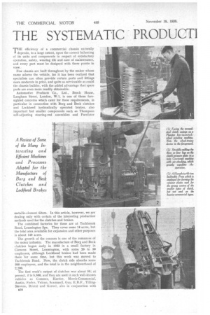
THE efficiency of a commercial chassis naturally depends, to a large extent, upon the correct balancing of its units and components in respect of satisfactory operation, safety, wearing life and ease of maintenance, and every part must be designed with these points in view.
Few chassis are built throughout by the maker whose name adorns the vehicle, for it has been •realized that specialists can often provide certain parts and fittings more moderate in price, and quite as serviceable as could the chassis builder, with the added advantage that spare parts are even more readily obtainable.
Automotive Products Co., Ltd., Brock House, Langham Street, London, W.1, is one of those foresighted concerns which cater for these requirements, in particular in connection with Borg and Beck clutches and Lockheed hydraulically operated brakes, also important but smaller components such as Thompson self-adjusting steering-rod assemblies and Purolator metallic-element filters. In this article, however, we are dealing only with certain of the interesting production methods used for the clutches and brakes.
The combined factories for these are at Tachbrook Road, Leamington Spa. They cover some 14 acres, but the total area available for expansion and other purposes is about 140 acres.
The growth of the concern is one of the romances of the motor industry. The manufacture of Borg and Beck clutches began early in 1932 in a small factory in Clemens Street, Leamington, with some 20 to 30 employees, although Lockheed brakes had been made there for some time, but this work was moved to Tachbrook Road. Now, the clutch side absorbs some 300 employees, and the total is in the neighbourhood of 2,200.
The first week's output of clutches was about 50; at present, it is 5,500, and they are used in such well-known vehicles as Commer, Karrier, Morris-Commercial, Austin, Foden, Vulcan, Scammell, Guy, E.R.F., TillingStevens, Bristol and Garner, also in conjunction with Perkins engines when these are supplied complete with clutches.
Actually, the clutches and brakes are made by separate subsidiary companies, but there are certain centralized departments, such as the heat-treatment, chemical laboratory, costing and planning, and research, although the experimental sections are separate.
The clutch consists essentially of a driving plate, with rings of friction material at each side; which runs between the fate of the flywheel and a pressure plate, the pressure being afforded by numerous coil springs; these and the release levers are contained in a pressedsteel cover.
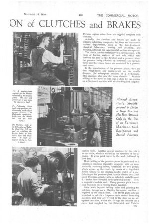
In the manufacture of the pressure plates, they are first rough-faced and finish-turned on the outside diameter (for subsequent location) on a Rydermatic. This machine also cuts the inner chamfer. Straddle milling of the three or four lugs is done by two cutters on a Cincinnati machine with air-chucking and tungsten carbide tools. Another special machine for this job is an Archdale, which is started by the operation of the air clamp. It gives quick travel to the work, followed by slow feed.
Hook milling of the pressure plates is performed on a Cincinnati machine especially equipped with an automatically reversing motor, controlled by two pedals, which screws up the chuck by Means of a dog-clutch device similar to the starting-handle clutch of a car. Grinding of the pressure-plate faces is effected on a John Lund Precimax grinder with an infinitely variable-speed d.c. motor direct-coupled to the grinding spindle. Here, a magnetic chuck4s used. Every pressure plate is carefully balanced on a rocking-frame machine.
Little work beyond drilling holes and grinding the bolt-hole facings on a Planitor horizontal machine is required by the clutch cover. The driven-plate hubs are broached in pairs in a Lapointe twin vertical broaching machine, and they are riveted to the discs on an airsqueeze machine, whilst the facings are secured on a clever tool supplied by the Bifurcated and Tubular Rivet Co., Ltd., in which the rivets are fed automatically from a hopper.
One particularly interesting machine employed for the commercial-type clutches is a CravenRigid horizontal and vertical There is a 100-per-cent. inspection at the end of the production line, and a " floating" inspector for individual operations.
Assembly is extremely rapid. The pressure plates are held to a table by clamps mounted on spiral spindles, so that they turn to secure the plate as they descend. Dial gauges are used to check the alignment of the withdrawal levers, each of which has an adjustment nut, to turn which electric box spanners are ern ployed, the nuts being pinned afterwards.
For the smaller types of clutch with sprung centres, the retainer plates are pressed out in a 66-ton Humphries Inclinable Press. The smaller clutches are dynamically balanced at 3,000 r.p.m., but the heavier types are balanced statically on parallel bars.
On the Lockheed brake side, several of the machines employed closely resemble those used in the manufacture of clutches, but there are some particular processes. For instance, the operating cylinders are machined first in an inverted rough borer, which allows the swarf to drop away without choking. In finish-boring of the integralbarrel type a clamp is used to balance the Cylinder, the casting being held on a self-locking spindle with rollers, resembling the device used on some forms of free wheel.
To prevent wear of the rubber cups the cylinder surface must be extremely smooth, and it is finished by a planishing tool consisting of a cage carrying taper rollers e36 inside which is a taper mandrel. This tool rotates at high speed and " rolls" the cylinder surface under considerable pressure.
For boring and facing operations on the cylinders, there is a new Churchill Goss and De Laeuw machine with four spindles and additional" tools for cutting the annulus, etc. This replaces five separate machines and saves 9 minutes to 10 minutes per cylinder. There is a large gang of four-spindle automatics of the Schutte type, supplied by E. El. Jones (Machine Tools), Ltd.
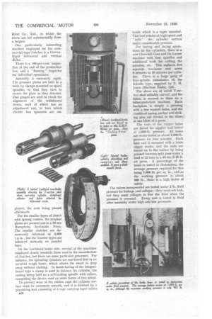
The shoes are of rolled T-section steel suitably curved, and the fabric is secured to these on a bifurcated-rivet machine. Each backplate is simply a pressing with a few reamed holes, and the combined spring anchor and striking pins are riveted to the shoes at one blow of a press.
The ends of the copper tubes are flared for nipples and -tested at 1,600-1b. pressure. All hoses are water-tested to about 2,500-1b.
pressure for four minutes. Each hose end is mounted with a brass nipple inside, and the ends are forced on to the rubber by being pressed between split jaws under a load of 22 tons in a 40-ton E.M.B. air press. A percentage of the hoses is tested to destruction, the average pressure required for this being 7,000 lb. per sq. in., and as the working pressure is about 900 lb., there is a high factor of safety.
The valves incorporated are tested under 2 lb. fluid pressure for leakage and collapse—they must not leak, but they must collapse to free the fluid when the pressure is reversed. Every unit is tested in fluid after assembly under high and low pressures.