


HAND AND FOOT IN BRAKE APPLICATION.
Page 26
If you've noticed an error in this article please click here to report it so we can fix it.
A Resume_ of Recently Published Patent Specifications.
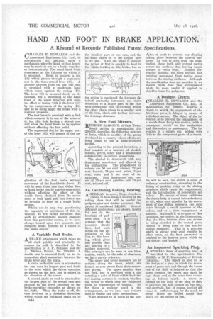
CHARLES EDWARDS and the ..Associated Equipment Co., Ltd., in specification No. 249,932, ' show a mechanism whereby hand or. foot levers may be made to act on a brake together or independently.. The usual band lever terminates at the fulcrum on which it IS' mounted. . From it projects i pin ,(A) which passes through a segmentd slot in the three-armed lever (C). A plunger extends from the pin (A) and is provided with a mushroom head which bears against the spring (B). The lever (C) is mounted freely on its fulcrum, but a, movement of the hand lever in the usual direction will have the effect of taking with it the lever (C)-by the compression of the spring (B), and by so doing apply the brake-with a resilient pressure.
The foot lever is provided with a link which connects it to one of the arms of C, but this link, having a slotted eye, will allow the hand brake to be applied without affecting the foot pedal.
ap plication of the foot brake without movement of the hand-brake lever. It will be seen from this that either foot or hand brake can be applied separately, without affecting the other, or the double force obtained from the movement of both hand and. foot levers can be brought to bear on a single 'brake system,
Whilst not in any way questioning the ingenuity or usefulness of this in-. vention, we are rather surprised that such an arrangement should emanate from this particular source, as we have always looked upon two separate and complete brake systems as a canon of bus brake design:
A Variable Pull Brake.
A BRAKE attachment which takes up
all slack quickly and gradually increases its pull, is described in the specification of j. F. Simpson and Sir A. Whitten Brown, No. 250,035. A double cam is mounted freely on an intermediate shaft somewhere between the brake lever and the brake.
A chain or flexible cord is attached to the cam near its largest part and leads to the lever which the driver operates, as shown on the left, and is pulled in the direction of the arrow.
A second hain or cord is attached to the largest part of the second cam and extends to the lever attached to the brake-operating expander, as shown on titd,right. When the brake is off, the cam revolves it a clockwise direction, which winds the left-hand chain on to
the smallest part of one cam, and the left-hand chain on to the largest part of its cam. When the brake is applied, the -action at first is quickly to haul in the 'chain..leading:.to .the.bralte, but as
the action is continued the leverage obtained gradually increases, one chain mounting to a larger part of the cam with consequent gain in leverage whilst the other chain winds to a smaller part of the cam, which still further increases the leverage obtained.
A New Fuel Mixture.
RENE DE SAR1GNY, of Cape 'Town, South Africa, in specification No. 250,019, describes the following mixture of fuels, which is another of the group developed in a country where efforts are being made to use a home-produced alcohol.
According to the present invention, a fuel consists of a mixture of alcohol, benzoic, petrol, ether and a denaturant substantially in certain proportions.
The alcohol is denatured with any denaturant sanctioned and allowed by the authorities. The proportions by volume are 50 per cent. alcohol, 12 per cent. benzoic, 34 per cent. petrol, 2 per cent. ether and 1 per cent, of denaturant. Said denaturant may consist of .25 per cent. pyridine and .75 per cent. mineral oil.
An Oscillating Rolling Bearing. A GERMAN inventor, Hugo Junckers,
. claims to have made a bearing of the rolling class that will be useful for gudgeon pins and similar purposes., The patent is numbered '242,600. Several different applications are shown, mostly for use in the bearings of gudgeon pins. It is strange that the inventor should have laid such stress on the application of his idea to this bearing, which gives less trouble than any bearing in a modern motorcar. The principle can be seen in our illustration, which, for the sake of clearness, we havz partly redrawn.
The upper and lower members are in contact along the faces, which are formed as arcs struck from their respective pivots. The upper member does not rock, but is provided with a pin carrying a pair of links which hold the two mating surfaces in contact, whether the stress to which they are subjected tends to compression or tension. So far there is nothing novel in the arrangement, as we have seen rockers used in chains and other mechanisms.
What appears to be navel is the pro vtsion of teeth to prevent any slipping taking place between the curved surfaces. As will be seen from the illustration, these teeth only extend partly across tbo surface, thus leaving ample
surface to resist wear. Besides preventing slipping, the teeth prevent any twisting movement from taking place between the mating suf-faces. Although the specification does not mention it, we should think that this arrangement might be more useful if applied to shackles than for gudgeons.
A Dashpot Clutch:
CHARLES K. EDWARDS and the
Associated Equipment Co., Ltd., in specification No. 249,931, deselibe a clutch in -which the engagement of the frictional parts is delayed by means of a dashpot action. The object of the in-' vention is to prevent the engagement of a clutch from being f too sudden, with a consequent strain on the mechanism and discomfort to passengers. The invention is a simple one, adding very little to the component parts of a clutch.
As will be seen, the clutch is quite of ordinary, construction, excepting in the fitting of packing rings to the sliding members which cause the engr.gement, and the introductiOn of non-return air valves. By means of these additions the clutch body is turned into a dashpot, as air, when once expelled by the movemoat of the sliding members, can only enter through a small aperture of the valves, and so a slow engagement is assured. Although it is no part of this invention, we notice, in the illustration, that the fibre friction discs are shown as being attached to the central plate instead of being fixed to the heavier sliding members. This is a practice which is giving very good results in other cases, as the heat generated is confined to the heavier parts, which do not distort and buckle.
An Improved Sparking Plug. A SPECIAL form of sparking plug is described in the specification No. 233,325, of M. F. Macdonald, Of British Columbia. The object is said to the design of a plug in which the movement of gases into and through the loiver end of the shell is induced so that the parts forming the spark gap shall be kept clean, and at the same time ensuring an intense spark. A sleeve is formed on the body of the plug so that ' it encircles the bell formed on the can; tral electrode, but, of course, -leavinground it .sufficient gap for the spark to"
occur. Holes are round 'this sleeve for the escape of gas.