


A Gas Turbine for Road Vehicles
Page 26
If you've noticed an error in this article please click here to report it so we can fix it.
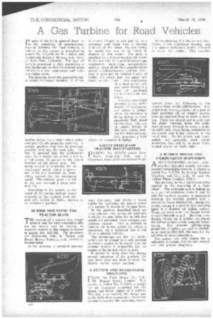
IN spite of the fairly general doubt as to the suitability of internal-combustion turbines for road vehicles, a scheme of this nature is described in patent No. 612,658, by W. Lindsey and Armstrong Siddcley Motors, Ltd., both of Park. Side. Coventry. The type of turbine proposed is that employing a heat7exehanger so that the exhaust gases emerge at a low temperature and without undue noise.
The drawing shows the general layout, in which the" output member (I) of the turbine drives, via a clutch and a reduction gear (2), the propeller shaft (3). A normal gearbox may also be provided, possibly built into the back axle. The fuel is sprayed into the combustion space by a nozzle (4), which is fed by a fuel pump (5) geared to the output member of the power unit. The pump output is controlled by an accelerator pedal, whilst a governor valve,. (h) exercises an overriding control for the maximum speed. The exhaust gases are led to the rear through a large conduit (7).
According to the patent, as the speed of the output turbine varies inversely is the applied load, the unit will, within its limits, operate as an automatic gearbox.
RUBBER MOUNTING FOR TRACTOR SEATS
THE motion of a tractor over rough ground can be very uncomfortable for the driver, and an attempt. to improve matters in this respect is shoWn in patent No. 612,702. The patentees are IYIetalastik, Ltd., R. Turner and David Brown Tractors, Ltd., Meltharn, Huddersfield.
In the drawing, a standard pan-seat
is shown, hinged at one end (1) to a silb-plate and fitted with a locating stud (2) at the other, the aim being to enable the scat• to be tilted to dispose of rain water. The plate is attached to a forked bracket (3) which fornis one link of a Parallelogram-type suspension, permitting up-and-down motion: Each of the four parallelogram pivots is rubber-bushed, and the resilience is provided by bonded blocks of rubber (5) which join the upper and
lower parallel links. The application of a load to the seat puts these blocks in a state of combined compression and shear.
A tractor seat which provides for an undue degree of movement, can prove a danger when the machine is being driven at comparatively high speed on the road. The use of rubber blocks in this way, whilst makina for increased cornfort, possesses a high degree of essential -damping.
SAFETY SWITCH FOR TRACTOR SELF-STARTERS
PA T ENT No. 612,674 comes from Harry Ferguson. Ltd., and I. Chambers, both of Fletchamstead High way, Coventry, and -shows a novel means for operating the starter switch of a tractor by means of the gear lever.
• In the gearbox described there are three selector rods, giving six positions in all for the gear lever, but as only five speeds are provided, there remains one. position unused. This is utilized to operate the starter switch (1), which is connected, via a bellcrank and a rod (2) to a selector rod (3).
The advantages are that the starter. switch can be placed in a safe position in which it dannot be damaged; also, the scheme renders it impossible for the engine to be started while in gear.
It should be made clear that during normal operation of the gearbox, the a,,lar "lever does not have to enter the electric starter switch position.
A CLUTCH AND BRAKE-PEDAL MOUNTING •
FROM the Ford Motor Co., Ltd., 88, Regent Street, London, W.1, comes, in patent No. 611,075, a design for an improved mounting for ,the clutch and brake pedals of a vehicle. The aim is to simplify the design and at the same time to provide.a means for counter-balancing the operating forces.
In the drawing, 1 is the normal sideframe, 2 the cruciform bracing, and 3 a . special additional girder provided to carry the pedals. "[his member reaches from the X-bracing to the inswept front of the 'side-member. The pedal-shaftbearing consists of a pair. of Steel pressings (4) of conical outline with an inturned boss to form a bearing. These are placed end to end with the girder between them, the pedal shaft, passing through to carry a pedal on each side, these being, connected. to the clutch and brake rodwork in the usual" way. As the clutch and "brake pedals are generally used .sirtuiltaneously, the, unit is, at most times, loaded evenly on both sides.
A RUBBER SPRING FOR INDEPENDENT SUSPENSION ,A SELF-DAMP1NG resilient rubber PA member, intended mainly fat-independent suspension systems, is shown in patent No. 612,701, by George Spencer Moulton and Co., Ltd., 13 and 14, Ashley Place,•Loridon, S.W.1. • The drawing shows .a typical assembly applied to the mounting of a front 1,1-1 1,1-1 heel. The stub-axle unit is linked on to a pair of wishbone forks (1 and 2), and the resilient member is positioned between the moving portion and a stationary frame bracket (4). Inside the rubber spring is a .central tube carrying upon it a number of sliding collars. These are fitted With thin flanges which extend outwards as at 5. Between these flanges, which act as guides, are placed the rubber collars which form the actual spring. The inherent self-damping properties of rubber are said to abolish, or at least to diminish, the need for the addition of shock-absorbers.
The system not only makes for a reduction in weight, but for low overall cost and greater simplicity.