


THE STEPHENSO N VALVE GEAR
Page 20
If you've noticed an error in this article please click here to report it so we can fix it.
Certain Characteristics of this Gear of Interest to the Technically Inclined.
T OOKING AT a wagon from the off side the direction of _L./rotation of the crankshaft is counter clockwise, and for a steam tractor with three-shaft transmission, clockwise.
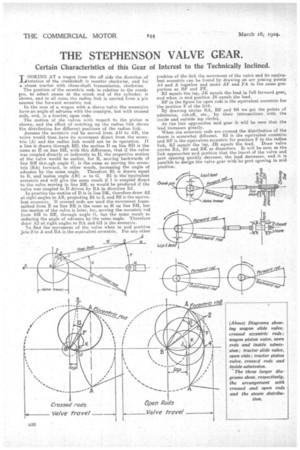
The position of the eccentric rods in relation to the crank. pm, to admit steam at the crank end of the cylinder, is shown, and in all .ises the radius link is carried from a pin nearest the forward eccentric rod.
In the case of a. wagon with a sleeve-valve the eccentrics have an angle of advance with the crankpin, but with crossed rods, and, ,n a tractor; open rods.
The motion of the valves with respect to the piston is shown, and the effect of notching up the radius link shows the distribution for different positions of the radius link.
Assume the eccentric rod be moved from. AD to AH, the valve would then have its movement, direct from the eccentric (A) and The radius link would not be in operation. If a line is drawn through BD, the motion D on line BD is the same as H on line B11, with this difference, that if the valve was coupled directly or indirectly to D, the respective motion of the valve would be earlier, for B, moving backwards of line BR thrcagh angle 0, is the .same as moving the eccentrio (BA) forward, in other words, increasing the angle of advance by the same angle. Therefore B1 is drawn equal to B, and makes angle AB1 = to G. B1 is the'equivalent eccentric and will give the same result if 1 is coupled direct to the valve moving in line BR, as would be produced if the valve was coupled to D driven by BA in direction BJ. In practice-the motion of D is in line DK, therefore draw A2 at right-angles to AB, projecting B1 to 2, and 11.2 is the equivalent eccentric. If crossed rods are used the movement transmitted from E on line BE is the same as H on line BH, but the motion of the valve is later, for, moving the eccentric rod from BH to BE, through angle 0, has the same result. as reducing the angle of advance by the same angle. Therefore draw AS at right angles to BA and G3 is the eccentric. To find the movement of the valve when in mid position join 2,to A and BA is the equivalent eccentric. For any other
position of the link the movement of the valve and its equivalent eccentric can be found by drawing an arc joining points A4 and A together and make AF and FA in the same proportion as Bbs and FE. BJ equals the lap, J.K equals the lead in fall forward gear, and when in mid position J4 equals the lead. BF in the figure for open rods is the equivalent eccentric for the position F of the link. By drawing circles BA, BE and B4 we get the points of admission, cut-off, etc., by their intersections with the inside and outside lap circles. As the link approaches mid gear it will be seen that the lead increases greatly. When the eccentric rods are crossed the distribution of the steam is somewhat different. B3 is the equivalent eccentric and BE is the equivalent, eccentric for position F in the radius link, BJ equals the lap, JR equals the lead. Draw valve circles BA, BE and BK as diameters. It will be seen as the link approaches mid position that the travel of the valve and port opening quickly decrease, the lead decreases, and it is possible to design the valve gear with 'no port opening in mid position.