


AN INGENIOUS DIFFERENTIAL GEAR.
Page 34
If you've noticed an error in this article please click here to report it so we can fix it.
A Résumé of Recently Published Patents.
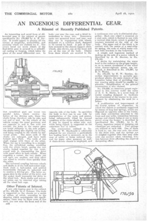
An interesting and novel form of differential gear is the subject of patent specification No. 176,063 by A. E. Jerram. It would appear to possess all the virtues of simplicity, accessibility, and economy which are claimed for it. The crown bevel (or worm wheel) of the final-drive gear is secured to a cylindelcal casting or forging, which takes the place of the usual differential case. In
this cylindrical part are bored two parallel holes, which receive the halves of the driving axle, these two shafts lying, therefore, side by-side, and not end to end. As, the wheels of the vehicle occupy the usual positions, and are opposite to and in line with one another, the holes in the centre piece are bored obliquely to the axle proper, the shafts being also slightly out of line, and being coupled to the wheels by universal joints. The inner ends of the shafts are enlarged, and have teeth formed upon them. The teeth of one shaft engage with those of the other. When thd car is travelling in a straight line, the cylindrical casing, revolving with the crown bevel, carries the two shafts, locked together by the teeth, round with it, transmitting the drive with equal effect ta both wheels. When rounding a corner, the two shafts can roll upon one another, and thus allow one wheel to revolve more quickly than the other.
The universal coupling between wheels and shafts is of the ball-and-socket type. Each shaft is ball-ended, and pierced transversely through its spherical end to receive a driving pin. The latter engages slots in the socket of the joint, and the socket itself transmits the drive to the wheel hub. Both shafts and universal joints can be removed after taking off the wheel hub caps.
Other Patents of interest.
A new side-tipping gear is the subject of No. 176,156, by J. Ochsner. The body is supported on the chassis on a series of rollers, of which, according to the drawing which accompanies the specification, there may be three rows of five each, one row near the front end of the A34 body; one near the rear, and a third in termediate to these two. Transverse racks are mounted front and rear, and they are in engagement with 'wheels mounted on a common shaft, designed to be turned by hand. A pair of brackets secured to the chassis support chain wheels, also shown, one at the front and one at the rear of thy body. Chains from these wheels are secured to the opposite side of the body. In operation the body is first run to one side by manipulation of the racks and pinion, being subsequently tilted by manual_ operation of the chain wheels and chains. It may be tipped to either side, and, while being tipped, is supported on the outermost line of rollers. .
The. construction outlined in No. 176,169 by W. Macdonald is admirably adapted for use wherever a particularly low loading level is necessary, as in the case of cattle or horse removal vans, and for many other purposes as well. A chain-driven chassis is employed, and a continuous rear axle is eliminated altogether. Each rear wheel is mounted on a stub axle, which is formed in one with. a vertical slide block, which is guided in brackets mounted on the side. of the body. The upper end of the block is in contact with the centre of a semi-elliptic spring, the ends of which make contact with brackets in the bodywork.
A simple and ingenious method of jacking up the axle of a motor vehicle is described by A. N. Shorter, in No. 176,161.
A. device for maintaining the water level in the radiator at the proper height, so as to ensure circulation of the water when thermo-siphorric means are employed, is described in No. 176,087, by E. O. Weeks,
No. 176,125, by H. W. Bamber, describes improvements in portable gasproducer plants, the main objects of the invention being that of previding. that any wearing parts should be readily replacable.— Simplification of the general construction is also claimed.
No. 176,029, an American patent registered in this country under the name of E. C. B. Marks, is a novel form of trailer coupling designed to facilitate the attachment of the tractor to its complement by eliminating the need for a helper. A modification and improvement of the Cowey system of suspension, in which the chassis is resiliently supported by means of long leaf springs, which are 'disposed on opposite sides of the frame, with their extremities attached to the front. and rear axles, connection between springs and chassis being at one or more points along the former, is &scribed in specification No. 176,051, by L. E. Cowey, ingenious means of damping out vibrations are embodied. Two springs are utilized at each side. One of them is fixed to, say, the rear axle, the other to the front axle, and the springs are socoupled together that they may slide over one another when vibrating, friction between them affording the required dampening effect. "