


Renewing Valve Seats
Page 72
If you've noticed an error in this article please click here to report it so we can fix it.
A Msumg of Recently Published Patent Specifications
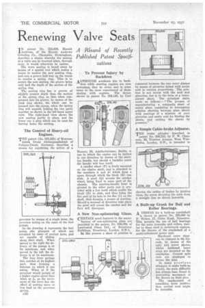
IN patent No. 352,856, Harold Andrews, of the Harold Andrews Grinding Co., Cheapside, Birmingham, describes a means whereby the seating of a valve can be renewed when, through wear, it would otherwise be useless. .The worn seating is bored away by means of a special tool which makes a recess to receive the new seating ring, and cuts a groove half-way up the recess to receive a spring ring. This is to secure the new seating, the groove being only half the depth of the section of the spring ring.
The seating ring has a groove of slightly greater depth than the section of the spring ring, so that when compressed into its groove, by means of the junk ring shown, the whole can be pressed into the recess, when the spring ring will expand, locking the two parts together as shown in the left-band upper view. The right-hand view shows the new seating partly in place, and the lower one a plug which can be used for forcing home the seating.
The Control of Heavy-oil Engines.
THE patent (No. 355,325) of Motorenfabrik Dents Aktiengesellschaft of Cologne-Dents, Germany, describes a means for regulating the action of a governor by means of a single lever, the governor acting on the cams of the fuel pumps.
In the drawing A represents the fuel pump, 4-the plungers of which are actuated by cams of conical form, and are capable of sliding .
along their shaft. When moved to the right the delivery of the pumps is at its minimum, and when moved to the left the delivery is at its maximum.
The long lever springs into notches at. its highest part, thus forming a fulcrum on which it can swing. When at S the governor would permit of a higher engine speed than when at L, as the movement of the lever has the effect of putting more or less load on the governor spring. To Prevent Injury by Backfires
ALTHOUGH accidents due to back fires while starting engines are rare nowadays, they do oceur, and in some cases to the most• experienced of those dealing with engines. The device shown in patent No. 356,149, by Carl Heuner, 28, Adalbertstrasse, Berlin, is one in which the engine can be turned in one direction by means of the starting handle, but should a backfire occur the handle will free itself.
A ratchet wheel (P) is freely mounted on the engine shaft, and is attached to the members A and Al which form a space through which the block (E) can slide. A pawl (Q) arrests the ratchet wheel, being fixed to some part of the
chassis. The starting-handle lever is pivoted to the other parts and is provided with a few teeth which enable the block (E) to slide, and thus bring the flat part of its hole to the flat (I) on the shaft, thus forming a means of starting. Should a reversal of direction take place the pawl will arrest the ratchet and the fiats will disengage.
A New Non-splintering Glass.
CERTAIN novel features in the manu facture of non-splintering glass are described in the patent, No. 356,394, of Laminated Glass, Ltd., of Broadway Buildings, Broadway, London, S.W.1.
In this process a sheet of gelatine is
cemented between the two outer glasses by means of glycerine mixed with acetic acid in various proportions. The gelatine is not mixed with the acid and glycerine, but is in the form of a transparent sheet. The principal claim reads as follows :—" The process of manufacturing a composite sheet of safety glass, consisting in interposing gelatine sheeting between glass sheets with coatings of a mixture of pure glycerine and acetic acid for binding the sheets, and uniting the sheets by pressure."
A Simple Cable-brake Adjuster.
THE brake adjuster described in patent No. 256,153, by E. W. Chapman, 26, Taunton Avenue, West Wimbledon, London, S.W., is intended to shorten the cables of brakes by kinking them, the screw diverting the cable from a straight line as shown herewith.
A Built-up Crank for Ball and Roller Bearings, A DESIGN for a built-up crankshaft is shown in patent No. 355,060 by
F. Wykes, 17, Glebe Road, Nuneaton. This permits the use of ball bearings for the main journals, and rollers, similar to those used in motorcycle engines, for the throws of the crankshaft of a multi-cylindered power unit. Hardened outer rings can be clamped in the bigends, by means of the split and screw shown, whilst hardened inner rings are mounted on the crankpins. Conical split nuts are employed to secure the pins.
In many previous attempts to make built-up cranks, the main difficulty has always been found in preventing movement of the throws on their pins.
The employment of something more positive than conical nuts might be desirable.