


Hydraulic Auxiliary Suspension
Page 49
If you've noticed an error in this article please click here to report it so we can fix it.
A System which Minimizes Frame Torsion and Provides for "No-load" Conditions ON July 29th, 1930, we described a suspension system which had been patented by Mr. George Dexter, now of " Alandene," Stoney Lane, Quinton, Birmingham Since that date various alterations have been made, partly by way of eliminating features which experience has shown to be unnecessary, and partly by additions to obtain further advantages.
In the first category may be mentioned the pumping system and the normalizing pipe. It has been found that the leakage of fluid from the cylinders, even after a long period, is so small as to be negligible. Consequently, it is not necessary to complicate the mechanism by including parts solely to compensate for any such loss.
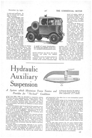
The chief innovation is the inclusion of a separate cylinder and spring-loaded plunger between each pair of main suspension cylinders. Whatever pressure may exist in the last nhined is thus transmitted by way of the third plunger to the coil spring, which banks it up. This spring, being considerably lighter than the main leaf springs, is able to follow moderate axle movements when the vehicle is carrying little or no load.
Another change is noteworthy, although it may possibly be regarded more asap alteration of detail design than of Principle. Instead of employing an hydraulic cylinder at each end of each road spring, the latter is carried by a tubular member pivoted at one end to the chassis frame and supported at the other (or at some intermediate point) by an hydraulic unit. Considering a front spring, in the simplest case the forward eye is pivoted together with the tube to the front dumbiron. At some point between the axle line and the rear end of the spring, an hydraulic cylinder is mounted on the chassis frame above the tube, on which a sliding lug connects with the plunger. The rear end of the spring is pivoted to a member which is free to slide in (or on)' the end of the. tube.
A further development is to mount the spring so that it can swing about the tube. It is thus relieved of twist when the vehicle is negotiating particularly uneven ground.
In action, supposing that one wheel is surmounting an obstacle while the opposite one has fallen into a depression, the plunger connected with the former wheel is forced up into its cylinder and liquid is displaced, thus forcing down the plunger on the opposite side. Consequently, both road_ springs remain normally loaded and the frame is not twisted.
In the pipe that connects the two main cylinders there can be fitted, if desired, an auxiliary cylinder, which, as has been mentioned, carries a spring-loaded plunger. An adjustment is provided for the buttress of the spring and so its effect as an auxiliary to the main springs can be varied to suit the loading of the vehicle. In any case, a stop is provided so that the spring cannot be overloaded.