


NOTE-S ON ENGINE LUBRICATION.
Page 14
If you've noticed an error in this article please click here to report it so we can fix it.
Advice Which Will be of Service to Users of the A-type Maudslay.
In the subvention A-type Maudslay engine the main crank, big-ends and gudgeon-pin bearings are lubricated by oil pressure from a rotary gearwheel pump, driven from the bottom of the vertical shaft, the cylinder walls being the only surfaces to rely on splash lubrication.
As one gallon of oil is sufficient to fill the base to the correct level, care must be taken to keep the oil pump and system in good condition, as failure of this vital component would obviously cause a great deal of damage. Should the pump fail to function none of the above-mentioned bearings would receive any lubricant, as the oil level is below the reach of the big-ends, and therefore there would be no splash of oil to lubricate the bearings.
The passage of the oil is as follows :— From the base the oil is drawn through a filter via a copper tube to the pump, and then forced to a distributing centre in the form of a brass casting situated on the near side of the base. From this centre there are four outlets : one each to the front, centre and rear main bearings, and one to an oil pressure indicator on the dash. There is also a small test cock for the driver further to test the oil pressure.
The main hearing liners are babbitt-metal lined, and have (or should have) grooves cut in them to coincide with the holes drilled in the crankshaft. The oil is then able to pass through the drilled crankshaft to the four big-ends and the two intermediate main bearings. Each big-end has (or should have) a small hole drilled to enable the oil to pass up through, the hollow connecting rods to the gudgeon pins. All surplus oil from these bearings is thrown about, lubricating the pistons and cylinder walls.
Should the pump fail to function the cause can often be traced to the oil filter being blocked. This can be remedied by releasing the wire retaining clip and removing the filter gauze, without removing the filter body, and thoroughly washing the gauze it petroleum. To do this the hand may be inserted through one of the oil-filling doors. The gauze may then be replaced, taking care to replace the wireretaining clip in its proper position. Pump failure will also occur if the copper tube or connections between the pump and filter are faulty, as air would be induced into the system. 3hould pump failure occur on the road, the base should be filled with oil to such a depth as to allow the big-ends to dip. This procedure should not be adopted unless it is absolutely necessary, as the bearings are not designed to be lubricated by splash. The oil e:30 pressure in the system will gradually lessen as the bearings wear, there being less resistance.
It is a somewhat common fault with Maudslay subvention A-type engines to leak oil through the crankcase-end cover, the oil dropping on the flywheel and being thrown, thereby causing a high oil consumption and the engine and clutch to get in a very dirty condition. When the engine is down for overhaul the matter can be rectified in the following manner.
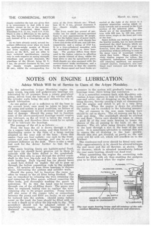
The oil runners in the rear main bearing liner should be cut as shown. The oil runners can be .4in. wide and deep. The crankshaft should be allowed no end float. Extra care should be taken to obtain a good fit of the rear main bearing to lessen the chance of the oil passing to the back of the oil thrower. The oil, after being thrown, drains bank to the base through a slot in the base of the end cover. It is sometimes advisable to enlarge this slot to ensure the oil draining to the base quickly. Should this slot get blocked, or partly so, the end cover will fill with oil, which will overflow on to the flywheel.
The crankcase-end cover should be fitted very carefully—approximately in should be allowed betweeiv the end cover and the oil thrower, as shown. The oil thrower, which is situated immediately behind the rear main bearing, should run dead true.
When assembling the engine the connecting rods should be filled with oil, thus enabling the gudgeon pins to be lubricated when the engine starts.;