


• Moving Floor With Auxiliary Roller Supports
Page 32
If you've noticed an error in this article please click here to report it so we can fix it.
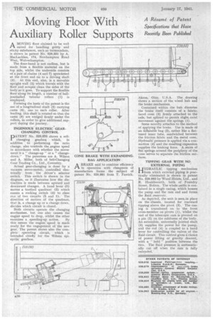
A Resume of Patent Specifications that Have Recently Been Published AMOVING floor claimed to be well suited for handling gritty and sticky Substances, such as tarmacadarn. is shown in patent No. 529,551 by A.
• MacLachlan, 174, Nei.vhamptou Road West, Wolverhampton.
The floor-band is not endless. but is made from a flexible material on the top side, whilst the underside consists of a. pair of chains (4 and 7) sprocketed at the front end on to a driving shaft (3). At this end, also, is a movable upright wall (2) which travels with the floor and scrapes clean the sides Of the body as it goes. To support the flexible floor along its length, a number of balljournalled tubular rollers (1) is employed.
Forming the basis of the patent is the use of a-longitudinal shaft (5) carrying ,cams (6), one to each roller. After loading, this shaft is rotated so that the cams (6) are wedged firmly under the rollers, in order to give additional support during the journey.
INGENIOUS ELECTRIC GEAR. CHANGING CONTROL
PATENT No. 528,676 shows a selfchanging gearbox which, in addition to performing the ratio change, also 'controls the engine speed in accordance with whether the movement is a " change-up " or a " change
. down." The patentees are A. Wilson and A. Miller, both of Self-Changing Gear Trading Co., Ltd.,. Coventry. Actual gear-changing is done by a vacuum servo-motor, controlled electrically from the driver's selector switch. This• switch is shown in the diagram, as it illustrates how the distinction is made between upward and downward changes. A hand lever (3) moves a toothed quadrant (2) which causes a rocking switch (4) to close one of two circuits (5 and 1). The direction of motion of the quadrant, that is, a change up or a change down, decides which circuit is closed.
Both circuits operate the changing mechanism. but one also causes the engine speed to drop, whilst the other exercises a speeding-up action. By this means the engine speed is made ready for the engagement of the new gear. The patent shows also the complete operating circuit, which is intended chiefly for the Wilson epicyclic gearbox. CONE BRAKE WITH EXPANDING. BAG APPLICATION
ABRAKE said to combine efficiency in operation with cheapness of manufacture forms the subject of patent No. 529,581 from T. Fawick
Akron, Ohio, U.S.A. The drawing shows a section of the wheel hub and the brake mechanism.
Contained within the hub diameter the brake itself consists of a fabricfaced cone (3) firmly attached to the axle; but splined to permit slight. axial movement against the springs (1).
Some novelty attaches to the method of applying the brake. Use is made of an inflatable bag (2), rather like a flattened inner tube, sandwiched between the friction fabric and the metal cone. Hydraulii pressure is applied via a connection (4) and the resulting expansion supplies the braking force. A series of flat springs around the periphery of the cone serves to separate the friction surfaces.
TIPPING GEAR WITH NO, EXTERNAL PIPING
HYDRAULIC tipping mechanism /from which external piping is practically eliminated is shown in patent No. 529,093 by Wood Hoists, Ltd., and R. Houldsworth, both of Foundry Street, Bolton. The whole outfit is contained in a single casing, which houses the pump and the ram end and forma the fluid reservoir.
As depicted, the unit is seen/in place on the chassis, located for rearward tipping above the pivot (3). The casing is trunnioned on to the front cross-member on pivots (1), whilst the end of the telescopic ram is pivoted on a pin (2) on the subframe of the body. An extensible, universally jointed shaft (5) supplies the power for the pump, and therod (4) is coupled to a band lever for controlling the valves of the fluid circuit. This control gives a, choice of power lifting or gravity descent, with a " hold " position between the two. The fluid pressure is automatically cut off when the ram is fully extended.