


Self-energizing Disc Brake
Page 74
If you've noticed an error in this article please click here to report it so we can fix it.
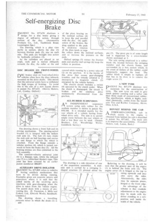
PATENT No. 857,674 discloses a design for a disc brake giving a degree of self-servo action, through motion of the disc. (Automotive Products Co., Ltd., Tachbrook Road, Leamington Spa.)
The drawing, which is a plan view partly in section, shows the disc (1) between friction pads (2), one on each side, The pads are brought into action by hydraulic cylinders (3).
As the cylinders are placed at an angle, each pad is moved obliquelytowards the disc, the roller at the end DISC BRAKES ON FRONT-WHEEL
niSC brakes uSed on front-wheel-drive
vehicles often have the discs inboard, mounted on the drive shafts. This means that the universal joints have to withstand the high torque of braking. To avoid this is the aim of a new layout shown in patent No. 857,633. (Morris Motors.
Ltd., Cowley, Oxford.) _ The drawing shows a front hub and its driving mechanism. The steering-swivel bracket (1) is integral with the hollow stub axle (2). The hub (3) runs inside the stub axle on ball bearings and carries an end flange to which the wheel is attached. From the flange extends a tubular portion (4), which is turned outwards to form the brake disc (5). All the braking stresses are thus contained in the hub assembly.
The constant-velocity universal joint (6) is a Rzeppa type, whilst the inboard one (7) is a rubberized Hooke's type. This joint has been covered by an earlier patent numbered 808,807.
AUXILIARY DRIVE ISOLATOR
PATENT No. 857,809 refers to vehicles having auxiliary mechanisms . that have to be driven during running. Examples given are concrete mixers and generators, where it is said that the added inertia of the revolving parts interferes with gear-changing when the drive is taken from the vehicle engine. The patent deals with a means of preventing this. (E. Twemlow, J. Mills and Fodens, Ltd., Elworth Works, Sandbach. Cheshire.) The drawing shows a travelling concrete mixer in which the drum (1) is B40
of the plate bearing on the inclined surface (4) to keep the pad parallel with the disc. On application of the brakes, the drag applied to the pads by clockwise rotation of the discs tends to urge the rollers down the inclined surfaces, and so increase the pressure on the pads.
Helical springs (5) retract the friction pads and smaller leaf-springs (6) keep the rollers in position.
rotated while running by a power take-off (2) on the gearbox. It is the inertia of this drive that causes gear-changing troubles, and the remedy adopted is to incorporate a magnetic clutch (3) energized by the vehicle battery.
The electric circuit includes a switch (4) operated by the clutch pedal. When the clutch is disengaged, the circuit is broken and the auxiliary drive momentarily disconnected from the gearbox.
ALL-RUBBER SUSPENSION
A N INDEPENDENT suspension IA system using only rubber for the resilient member is shown in patent No. 858,168. it is intended mainly for the rear wheels of a vehicle having frontwheel drive only. The aim is to permit ample room between the rear wheels so that a low floor can be used. (Dennis Brothers. Ltd., Woodbridge Works. Guildford. Surrey.)
The drawing is a side elevation of one of the suspension assemblies. A. stubaxle unit is carried by a swinging Lshaped structure (1) pivoted about the pin (2). The pivot pin is of some length and is supported by a cross-member shown sectioned at 3.
The sole spring employed is a rubber block (4), located between the swinging member and the chassis frame, and surrounded by a box section which, in the event of failure of the rubber, could temporarily support the load. The rubber block is simple to replace; all that has to be done is to remove the single screw (5).
A NEW TYRE PATENT No. 857,379 discloses new materials for the construction of tyres. The new tyres are said to give much quieter running and a softer ride than those made of conventional rubber. The specification, which is highly technical chemically, conies from the Goodyear Tire and Rubber Company, Akron. Ohio, U.S.A.
BONNET BEHIND THE CAB
A FORWARD-CONTROL cab in 1.-1 which access to the engine is obtained from behind the cab is described in. patent No. 857,662. The main aim is to improve the accessibility. (Vauxhall Motors, Ltd., Luton, Beds.) •
Referring to the drawing, it will be seen that the greater part of the engine (I) is behind the front axle (2). The engine cover (3) is hinged at the top to
BS 7, RCM swing upwards and may also carry the sides. Alternatively, the sides may be separate pieces. hinged, at the front edge.
An advantage of the scheme is that roadside adjustments to the engine may be made with the driver standing in a safe position well inside thc width of the vehicle.