


A Self-supercharging Engine
Page 60
If you've noticed an error in this article please click here to report it so we can fix it.
A Résumé of Patent Specifications that Have Recently Been Published
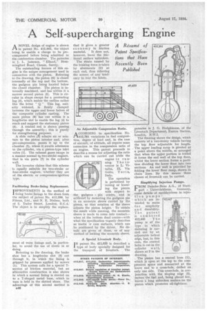
ANOVEL design of engine is shown in patent No. 412,562, the object being to enable a charge to be precompressed before being admitted to the cohabustion chamber. The patentee is J. L. Jameson, " Elland," Hem-. mingford Road, Cheatn, Surrey.
The outstanding feature of this engine is the unique arrangement used in connection with the piston. Referring to the drawing, the piston (6) is closed internally at the top and the bottom, the gudgeon pin being located below the closed chamber. The piston is internally machined, and has within it a narrow second piston (5). This is circular in shape except for a protruding lug (4), which makes the outline rather like the letter " Q." This lug, suitably widened, is firmly clamped between the upper and lower halves of the composite cylinder casting. The main piston (6) has cut within it a lengthwise slot to enable the lug (4) to reach and support the stationary piston (5). A Central rod, is shown passing through the assembly ; this is purely for strengthening purposes.
A slide valve (3) admits air or mixture to the piston interior and, after pre-compression, passes it up to the chamber (2), where it awaits admission to the cylinder, via a piston-type inlet valve (1). The exhaust gases escape in a manner normal tq two-stroke engines, that is via ports (7) in the cylinder wall.
The inventor claims that this scheme is equally suitable for two-stroke or four-stroke engines, whether they are of the electric or compression-ignition type.
Facilitating Brake-lining Replacement.
IMPROVEMENTS in the method of fixing brake linings to the shoes form the subject of patent No. 412,299, by Fibrax, Ltd., and N, E. Nielsen, both of 2, Tudor Street, _London, -E.C.4. The object is to simplify the replace
me it of worn linings and, in particuhr to avoid the use of rivets in so doing.
Referring to the drawing, the brake shoe has a lengthwise slot (3) cut through it, in which the lining is gripped by pressure applied by screws (1). This system calls for a special Tsection of friction material, but an alternative construction is also shown in which a normal lining is riveted on to a T-shaped metal base, which in turn is held in the slotted shoes. The advantage of this second method is B46 that it gives a greater economy in friction material. It does not, however, leave the frictional surface unbroken.
The strain caused by the braking force is taken by abutments (2) at each end, thus relieving the screws of any tendency to tear the fabric.
An Adjustable Compression Ratio.
A CCORDING to specification No. .1-1412,781 variations in fuel composition, degree of load and, in the case of aircraft, of altitude, all require some correction in the compression ratio of an engine. This patent proceeds to describe a means for adjusting the ratio which can be carried out while the engine is running. The inventor is L. Vitalba., 15, Via Goito, Turin, Italy.
The operation is performed by raising or lowering the piston with respect to the gudgeon pin centre, and is achieved by mounting the gudgeon pin in an eccentric sleeve carried by the piston, so that rotation of the sleeve adjusts the piston height. To obtain the result while running, the eccentric sleeve is made to come into contact— when at the bottom dead centre—with what the specification vaguely describes as knobs or cam surfaces, which can be positioned by the driver. No details are given of these, or of any method of locking the eccentric sleeve.
A Special Livestock Body.
IN patent No. 411,635 is described a type of body specially designed for the transport of livestock. The patentee s J. G. Hodgkinson, of the Livestock Department, Euston Station, London, N.W.1.
The drawing shows the design, which consists "of a two-stoMy vehicle having the 'top floor adjustable for length. The upper loading ramp is pivoted at a point above the middle, so arranged that when the upper portion is folded it forms the end wall of the top floor, whilst the lower section forms a partition dividing the lower floor into two sections. An end wall is provided by folding the lower floor ramp, shown in chain lines.By this means three classes of livestock can be carried.
Simplifying Injection Pumps,
FROM Daimler-Benz A.G., of Stuttert Untertfirkheina, Germany, come details of modifications in injec tion pumps which' are intended. to make
to r simplicity an d durability. The patent is "numbered 412,445 T h e puinp is of the type in which metering is carried out by an adjustable helical edge, but, in this case, the control helix is cut in the cylinder w a l l, shown at 2 in the drawing. The piston has a central bore (1), which is open at the top to the compression space and connected at the lower end to a cross-hole, drilled on only one side. This cross-hole, in conjunction with the sloping edge (2), • meters the fuel and, being placed low, leaves a' long unbroken surface .on the piston which promotes oil-tightness.