


VTIONARY POWER SYSTEM
Page 67
Page 68
Page 73
If you've noticed an error in this article please click here to report it so we can fix it.
ROM PERKINS By John F. Moony A.M.I.R.T.E.
WHATE VER may be the disadvantages of the steam engine as a means of propulsion, there is no doubt that many automotive engineers wish they could find a way of returning to the steam engine's power characteristics of constant horsepower and maximum torque at zero speed, even if only because of dispensing with a clutch and gearbox. Various attempts have been made over the years to reproduce these characteristics with internal-combustion engines, but few designs have looked hopeful even, let alone been successful.
On Tuesday, however, a paper was presented to the automobile division of the Institution of Mechanical Engineers which could mean far-reaching changes in vehicle propulsion. The paper had the rather frightening title of " Some experiences with a differentially supercharged diesel engine". but this gives little indication of its importance. The paper is the work of three authors: Mr. J. G. Dawson and Mr. W. J. Hayward, who arc respectively the director of engineering and the manager of the experimental department of F, Perkins Ltd., Peterborough, and Dr.-Trig. P. W. Glamann, the German engineer. All the work referred to in the paper has been carried out by Perkins and, furthermore, actually put into practice in a remarkably successful manner.
In simple terms, what Perkins have done has been to apply
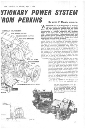
a supercharger to a perfectly standard 6.354 diesel engine and drive the blower through a differential gear train so that the usable torque is increased by 60 per cent and is greatest at about 1,400 r.p.m., being about half this value at maximum speed. The power is taken through a torque converter incorporating a lock-up clutch and then either through a simple forward-and-reverse gearbox with direct drive or a two-speed version (to give greater gradient performance) straight to the rear axle, so giving automatic, two-pedal transIniSSiOn. In this way a relatively small engine like the Perkins 6.354 5.8-litre unit. can cope very ably with nearly 25 tons.
That then, in a nutshell, is what the paper is all about, but the theory and application are—
naturally enough—considerably more involved than this. The paper is the first public announcement of this design project, which was started in 1957 and has been one of the best-kept secrets in the motor industry. I was let into the secret about 18 months ago, but only during the last four months or so has there been any whisper of this design exercise, and even then most of the rumours were well wide of the mark. And this despite the fact that reference to the system and a diagram of its application were reproduced in our issue of September 20, 1963, with respect to an earlier I.Mech.E. paper prepared by Mr. Dawson and. his colleague Mr. Vulliarny.
It must be emphasized that work on this power system (and I use the expression "power system" deliberately, for this is not merely an engine development) is still very much in the experimental stage. What has been done so far, however, does indicate the tremendous advantages to be gained from the use of such a system, and it is unlikely that any problems will arise henceforth which would halt the eventual development of a comrnercially-acceptable power system for virtually any size of diesel engine, and even petrol engines. , To understand the theory behind a differential diesel engine (Perkins refer to it as the " ODE"), it is necessary to look briefly at a diesel engine's fuel requirements. Broadly speaking, an engine delivers power in proportion to the weight of air and fuel pumped through it: it is comparatively simple to pump in the weight of fuel required at any given speed, but the problem is to supply the weight of air.
The power supply of a reciprocating engine is normally limited not only by the air the .engine can consume but also by mechanical loads, stresses and thermal loading. Thermal loading should not be a major problem, even in highlypressure-charged engines, as attention to piston cooling and heat-flow paths can be made in the design stages.
A given engine can usually deliver its maximum safe output irrespective of rotational or piston speeds, whilst in high-speed diesel engines in general, inertia loads at high speeds are more detrimental than combustion loads at low engine speeds, and it must be remembered that an automotive engine spends much of its life in the upper end of the speed range.
In theory, then, a substantially "constant power" engine seems feasible, and if it were obtainable the gearbox would be unnecessary and the steeply backing-up torque curve (similar to that of a steam engine) Would give an uninterrupted supply of power to the driving wheels.
Normal supercharging, either mechanical or exhaust-driven, tends to aggravate the faults of a normally aspirated diesel engine by increasing the horsepower .available at high rather than at low engine speeds. What is required is more power at low crankshaft (and road) speeds, and to overcome this with existing engines multi-step gearboxes are essential.
One way to get low-speed power is to apply a turbocharger with a waste-gate, such as that developed by Dr. Meurer, of M.A.N., and described in our issue of September 13, 1963. By using a waste gate, the charging at low engine speeds can be increased, and as the gate opens when the engine speed rises (in effect), the degree of blowing is reduced accordingly. One disadvantage is that a waste gate usually cannot be made to "fail safe", and if failure should occur the blower would burst.
The differentially supercharged system overcomes this. Dr. Glamann has been work ing on this principle for a number of years, and while he was with the French Berliet company a vehicle was built in 1954 with a differentially supercharged power unit. That it was not successful was probably because of the lack of a suitable supercharger, and in this respect Perkins were lucky in that Sir George Godfrey and Partners Ltd., were already making a screw-type blower for aircraft use which has basically proved ideal for the DDE.
The Glamann principle is quite .simple in that it consists of an epicyclic differenial gear located at the output end of the engine crankshaft. The engine drives the planet carrier, the sunwheel is connected to drive the supercharger, whilst the ring gear (annulus) provides the power output to drive the vehicle and acts also as a reaction member for the supercharge' drive. To understand how the gearing works, it must be remembered that a differential gear train is essentially a torquebalancing mechanism. This being so, the gear train so divides the engine's output torque that under all conditions of load a constant torque proportion drives the supercharger. Furthermore, the differential behaves as an overdrive also, • the ratio being automati
cally varied so that it is lowest at low• road speeds and highest at high engine or road speeds: in the Perkins unit the step-up ratio under full load conditions varies from 1-14 to 1 at low engine r.p.m. to 1-25 to 1 at maximum engine speed, and this helps give the diesel engine a wide speed range comparable with that already given by petrol engines.
The first Perkins DDE unit employed the original Glamann layout, as used in the Berliet vehicle, which incorporated a mechanical clutch, between the crankshaft and the differential gearing. This unit had a. prototype •B.I.C.E.R,A. lobe-type compressor as being the most suitable unit readilyavailable at the time, and the power output Was well short of the target, mainly because thefl maximum fuel-pump capacity• had been reached. This unit was, however, installed in a vehicle, and its performance with a three-speed gearbox encouraged further research.
The next stage was to dispense with the clutch and gearbox and find a suitable torque converter. The second-phase unit therefore incorporated a converter, the pump being driven by the annulus of the .differential: at the same time the screwtype compressor was adopted and Work on the fuel pump and an air-to-air heat exchanger(to give full charge cooling) achieved the target im.e.p. of 255 p.s.i. at 1,200 r.p.m. The torque-converter characteristics were such that the engine crankshaft speed at which the maximum m.4. was developed had to be changed to 1,150 r.p.m. later,. whilst subsequent developments led to a matching .speed of 1,450 r.p.m.• being adopted.
This unit gave a peak outputhorsepower of 147 b.h.p., but at 3,550 r.p.m. this fell-to 133 b.h,p. and it was felt that the maximum power was developed too low down the engine speed range and that the power 'at maximum speed was too low. As the maximum exhaust temperature under these conditions was only 600°C (1,112°F), further improvement was possible, so the third-phase units had more highly developed fuel pumps which gave increased delivery at higher engine speeds.
Meantime, development work on the torque converter itself had been under way. The original converter had a stall torque ratio of 3-1 to 1 and this, with the engine performance achieved at the second stage, gave an overall torque ratio of 6-5 to 1, which was barely sufficient for most commercial vehicle applications. Changes to the converter blading gave a stall ratio of 3.6 to 1, increasing the torque ratio to 7-55 to 1, whilst a lock-up clutch was introduced also.
The wisdom of incorporating a high degree of charge cooling was patently obvious, as in this way a 50°C reduction in exhaust temperature was obtained for a power increase of 17 per cent, whilst the specific fuel consumption was improved also. With charge cooling the engine b.m.e.p. was 255 p.s.i. (180 p.s.i. at the output shaft), whilst without the respective figures were 230 and 160 p.s.i. The engine rn.e.p. figures of 255 p.s.i. with charge cooling is equivalent to about 600 lb. ft. torque—a remarkable figure for a four-stroke diesel of 5-8-litres capacity! Even the usable m.e.p. of 180 p.s.i. is equivalent to 420 lb ft. torque (at 1,350 r.p.m.).
it is interesting to look at some of the engine figures relative to the third (and latest) stage of development, For instance,
PE 5° EEO
MGME
at 1,350 r.p.m. the engine horsepower is 155 b.h.p., with an output horsepower of 122 b.h.p.: at 2,800 crankshaft r.p.m. these figures are 176 b.h.p. and 156 b.h.p. respectively. At 1,350 r.p.m. the supercharger horsepower is 33 b.h.p., whilst at 2,800 r.p.m. the figure is 20 b.h.p. At 1,350 r.p.m. the fuel delivery is 108 cu. mm./stroke, the air-mass flow is 22 Ib./min. and the supercharger pressure ratio 2.4, and these figures become 73 cu. mm./stroke, 30 lb./min. and 1-5 respectively at 2,800 r.p.m. The maximum exhaust temperature is 640°C at 2,800 r.p.m. (450°C at 1,350 r.p,m.), whilst the specific fuel consumption at 1,350 r.p.m. is 0-376 pint/b.h.p./hr.—at 2,800 r.p.m. the figure is 0-415 pint/b.h.p./hr.
A power unit giving the figures mentioned above and working in conjunction with a 3.6-to-1 torque converter with lock-up clutch and a two-speed-and-reverse gearbox was installed in a 20-ton six-wheeler, and the performance was compared with similar vehicles equipped with a standard 6.354 and a turbocharged 6.354 developing 150 b.h.p. at 2,800 r.p.m. and 325 lb. ft. torque at 1,800 r.p.m. (this is an engine development which has yet to be announced). The comparative tests showed that the DDE-powered vehicle could achieve a far higher average speed over difficult test courses than the turbocharged model, and that for a given average speed and vehicle weight the fuel consumptions obtained with the DDE were the same or better than those given by the normally aspirated 6.354, whilst even compared with turboblown 6.354 fuel-saving advantages were apparent.
Turning to the actual components employed in this power system, the torque converter has been produced by the German firm of Klein, Schanzlin und Becker, and is capable of operating at speeds up to 4,500 r.p.m.: allowing for the 1.43-to-1 overdrive effect of the differential gearing, at the nominal governed engine speed of 2,800 r.p.m. the input speed to the torque converter is 4,000 r.p.m. The Godfrey-built rotary-screw-type compressor (known also as the Lysholm or S.R.M. type) has a cast-iron casing—the original aluminium casings having caused too much noise. Its maximum speed is 9,000 r.p.m.: half the safe limit.
C.A.V. Ltd., were concerned with the development of the fuel-injection equipment, and a special DPA distributor-type pump is employed, this having a cam ring with an increased lift and a hydraulic head with more than one filling port, features increasing the pump delivery to the required figure of 108 cu. mm./stroke. C.A.V. devised an alternative to the torque-screw system of delivery control whereby the governor is arranged so that it operates on the metering-valve orifice to decrease this with increase in speed. During the course of development, it was found necessary to increase the nozzle breaking pressure to 240 atm. to overcome the problem of blowback of gas into the fuel-injection system.
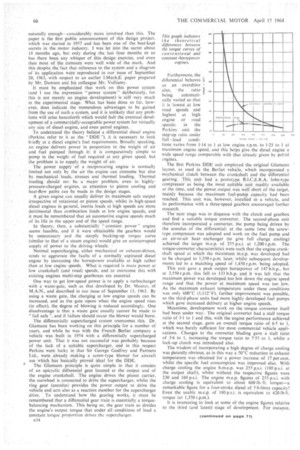
Mechanically the • 6.354 DDE unit is virtually identical to the turbocharged 6.354, incorporating heavier gudgeon pins, connecting rods and so forth than the normally aspirated unit, whilst various types of special cylinder head gasket and boresealing rings have been experimented
with, the type of ring at present in use being 0-12 in.
thick, with a Nimonic sheath and mild steel interior lamina tions. Cylinder head joints have presented one or two problems as the peak pressure at 1,350 r.p.m. is about 2,150 p.s.i., the figure at 2,800 r.p.m. being approximately 1,850 p.s.i. The standard Glacier reticular aluminium-tin shell bearings have, however, operated without trouble at calculated maximum pressures of up to 8,000 p.s.i.
So far as the transmission line is concerned, two basic types of gearbox have been developed, one having a single forward speed and the other having two speeds, and in both cases a very simple but effective hydraulic retarder can be incorporated. In the single-speed box forward and reverse gears are engaged by means of hydraulic clutches. The two-speed gearbox has a Ravigneaux-type epicydic train, this having three long and three short planet wheels and two sunwhcels to give the requisite ratios in the most compact way. High gear is direct, low is 1.8 to 1 and reverse is 1•27 to 1.
The hydraulic retarder, is particulary neat, and is directly connected to the output shaft. It employs the same hydraulic fluid and heat exchanger as the torque converter, as neither requires the use of thc heat exchanger at the same time.
Obviously there is not much point in developing a power system such as the complete DDE design if it has no advantages over a conventional engine and gearbox. What are the advantages, therefore? To begin with the 6.354 DDE and twospeed transmission with hydraulic retarder have an overall length (including fan) of approximately 78 in., whilst the overall depth without air cleaner is approximately 40 in. A typical 150 b.h.p. straight-six diesel with six-speed gearbox has an overall length of about 94 in. and a depth of just over 44 in. When it come,s to weight the same DDE set-up is 1,800 lb. dry, which is nearly 500 lb. less than the engine-gearbox combination referred to—and this despite no attempt having been made at weight saving so far.
When the single-speed box without retarder would give a satisfactory performance, a further 280 lb. can be saved compared with the two-speed unit: to compensate for the low engine-braking effect, an exhaust brake could be fitted.
This power system becomes more attractive as the gross vehicle weight increases, and the 6.354 DDE can cope with 85 percent more payload than the standard 6.354 and 45 per cent more than the turbo version. The improved economy lies mainly where high loads or speeds are required. For example, one of the Perkins test vehicles has given 8.5 m.p.g. at 18 tons and 7-6 m.p.g. at 20 tons while averaging 30 m.p.h. over a hilly country route. When a conventional diesel engine of just over 6-litres capacity was installed in the same vehicle, it was impossible to average 30 m.p.h. over the same route.
Another advantage is that the engine operates at a lower speed (the crankshaft speed rarely exceeds 2,000 r.p.m.) and the lower potential wear rate can be expected to outweigh any effect of the higher m.e.p. So far as cost is concerned, these are early days yet, but Perkins directors have every hope of being able to market the complete power system at less than the cost of a typical present-day 150-b.h.p, diesel alone.